
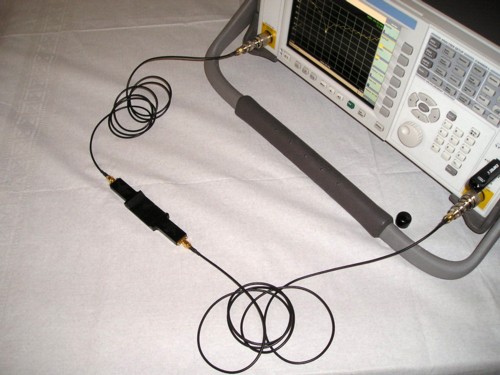
Figure 1. Measuring Loop to Loop Coupling for a Pair of Square Shielded Loops
Abstract: Shielded magnetic
loops are used to reduce electric field coupling to the loop and square
magnetic loops are useful for coupling signals into a PCB or measuring
noise in a circuit. However, significant electric field coupling can
still occur with shielded loops. One case of electric field coupling between a pair of shielded loops is presented
which results in a significant resonance between the shielded
loops. Such a resonance can cause errors in signal injection used for troubleshooting circuits.
Discussion: Figure 1 shows an overall view of the test comprised of a pair of square shielded loops connected to an Agilent N1996A spectrum analyzer set
up to perform a two port insertion loss measurement. The two loops are
positioned end-to-end and held in place with paper tape on the back
of the loops. A close-up of the two loops is shown in Figure 2. The
semi-rigid coax used to form the loops is encased in the plastic seen
in the figures.
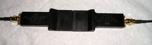
Figure 3 shows the resulting plot of insertion loss (unnormalized) between 10 MHz and 1 GHz. Notice the significant dip of around 30 dB at about 394 MHz. This feature has the appearance of a resonance that can be explained with reference to Figure 4.
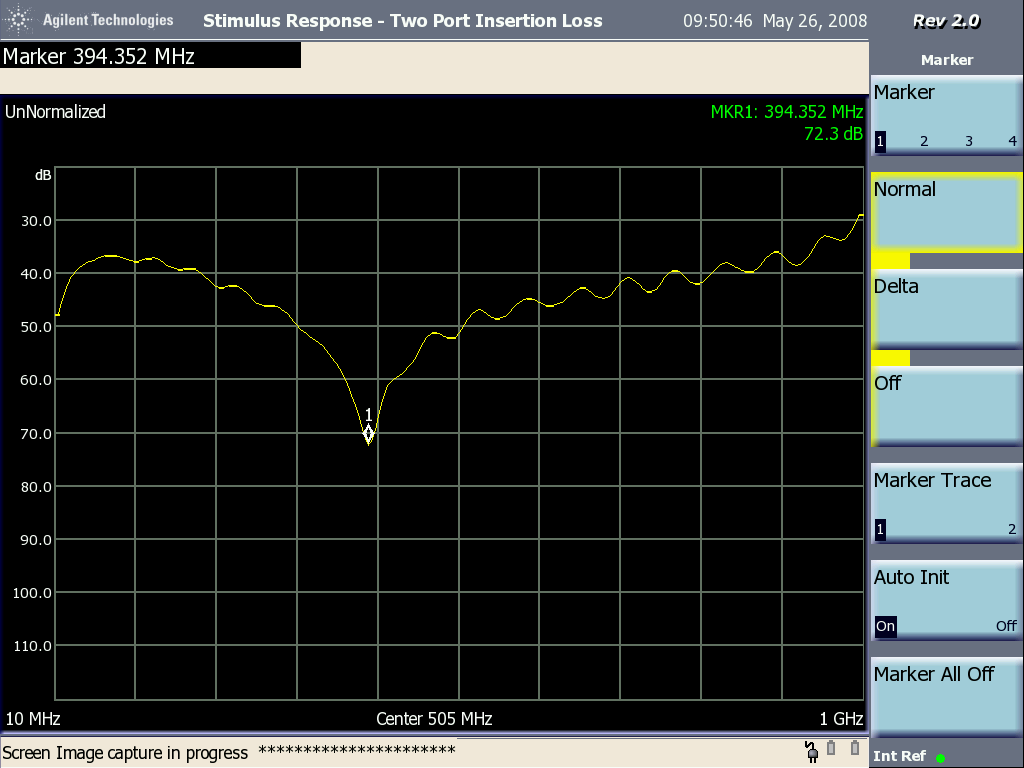
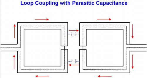
The capacitance between the shield segments shown in Figure 4 form a resonant circuit with the inductance of the two loops. The current path for the resonance is shown by red arrows. The loops I used were one inch on a side, so the effective loop for the resonant circuit is approximately two inches by one inch. The Missouri University of Science and Technology inductance calculator gives an inductance of about 125 nH for such a loop assuming a wire (shield) radius of 10 mils. The resonant frequency of 394 MHz then yields a capacitance of about 1 pF for the total capacitance in the tuned circuit of Figure 4. But how is energy coupled into this resonant circuit? There are a number of ways to explain how this happens, but the important point is that it does happen. Adding ferrite to the coax cables feeding the loops did not change the characteristics of Figure 3 so the current loop of Figure 4 is the controlling feature.
One possible simplified explanation is as follows: Current flowing in the center conductor of the driven loop generates inductive voltage drop (Ldi/dt) around the loop. A shielded cable is nearly an ideal transformer, so the voltage drop on the center conductor under each of the two shield segments is magnetically coupled into the shield segments as Mdi/dt. The mutual inductance, M, between the center conductor and the shield, is the inductance of the shield itself. This driving voltage on the two shield segments causes current to flow around the four shield segments coupled by the parasitic capacitance between the loop shields as shown in Figure 4 thus driving the resonant circuit. In this discussion, I am treating the circuit as composed of lumped elements since each segment and the loops themselves are small compared to a wavelength at 400 MHz.
If a resonance caused by the current path of Figure 4 is the reason for the dip in plot in Figure 3, then moving the loops apart should increase the resonant frequency. This would happen because the capacitance between the loops is reduced. Figure 5 shows the test setup modified to space the loops one cm apart. The two loops are taped to a plastic ruler to maintain the spacing during the measurement. A close-up of the spaced loops is shown in Figure 6.
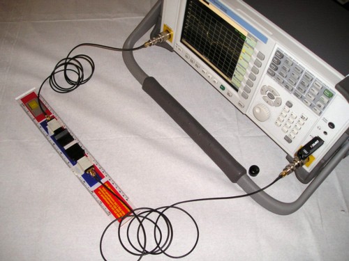
Figure 5. Measuring Loop to Loop Coupling for a Pair of Square Shielded Loops at One cm Spacing
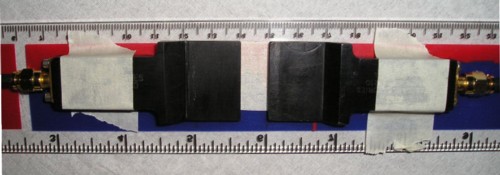
Figure 6. Close-up of Loops for Coupling Measurement at One cm Spacing
The resulting two port insertion loss plot is shown in Figure 7. Note that the resonant dip has moved to about 495 MHz. This would represent a significant drop in capacitance on the order of 40%.
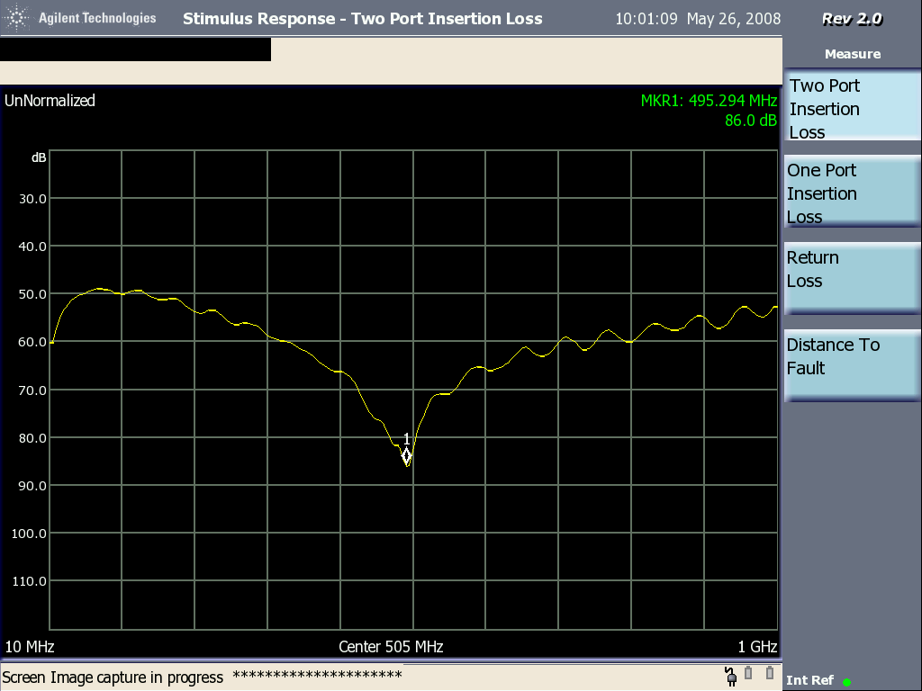
Figure 7. Plot of Loop to Loop Coupling With 1 cm Spacing and ~495 MHz Resonance
As the loops are moved further apart, the capacitance between all parts of the loops begin to contribute an increasing portion of the capacitance between the loops complicating the picture somewhat. One would not expect the capacitance to decrease as much as just that of the facing sides as the loops are separated.
A future Technical Tidbit will show how this effect can result in errors during troubleshooting a circuit using signal injection. The problem is that using a shielded loop can sometimes give a false sense of security that electric field effects are not important.
Figure 2. Close-up of Loops for Coupling Measurement
Figure 3 shows the resulting plot of insertion loss (unnormalized) between 10 MHz and 1 GHz. Notice the significant dip of around 30 dB at about 394 MHz. This feature has the appearance of a resonance that can be explained with reference to Figure 4.
Figure 3. Plot of Loop to Loop Coupling Showing ~394 MHz Resonance
The capacitance between the shield segments shown in Figure 4 form a resonant circuit with the inductance of the two loops. The current path for the resonance is shown by red arrows. The loops I used were one inch on a side, so the effective loop for the resonant circuit is approximately two inches by one inch. The Missouri University of Science and Technology inductance calculator gives an inductance of about 125 nH for such a loop assuming a wire (shield) radius of 10 mils. The resonant frequency of 394 MHz then yields a capacitance of about 1 pF for the total capacitance in the tuned circuit of Figure 4. But how is energy coupled into this resonant circuit? There are a number of ways to explain how this happens, but the important point is that it does happen. Adding ferrite to the coax cables feeding the loops did not change the characteristics of Figure 3 so the current loop of Figure 4 is the controlling feature.
One possible simplified explanation is as follows: Current flowing in the center conductor of the driven loop generates inductive voltage drop (Ldi/dt) around the loop. A shielded cable is nearly an ideal transformer, so the voltage drop on the center conductor under each of the two shield segments is magnetically coupled into the shield segments as Mdi/dt. The mutual inductance, M, between the center conductor and the shield, is the inductance of the shield itself. This driving voltage on the two shield segments causes current to flow around the four shield segments coupled by the parasitic capacitance between the loop shields as shown in Figure 4 thus driving the resonant circuit. In this discussion, I am treating the circuit as composed of lumped elements since each segment and the loops themselves are small compared to a wavelength at 400 MHz.
Figure 4. Circuit of Parasitic Resonance
If a resonance caused by the current path of Figure 4 is the reason for the dip in plot in Figure 3, then moving the loops apart should increase the resonant frequency. This would happen because the capacitance between the loops is reduced. Figure 5 shows the test setup modified to space the loops one cm apart. The two loops are taped to a plastic ruler to maintain the spacing during the measurement. A close-up of the spaced loops is shown in Figure 6.
Figure 5. Measuring Loop to Loop Coupling for a Pair of Square Shielded Loops at One cm Spacing
Figure 6. Close-up of Loops for Coupling Measurement at One cm Spacing
The resulting two port insertion loss plot is shown in Figure 7. Note that the resonant dip has moved to about 495 MHz. This would represent a significant drop in capacitance on the order of 40%.
Figure 7. Plot of Loop to Loop Coupling With 1 cm Spacing and ~495 MHz Resonance
As the loops are moved further apart, the capacitance between all parts of the loops begin to contribute an increasing portion of the capacitance between the loops complicating the picture somewhat. One would not expect the capacitance to decrease as much as just that of the facing sides as the loops are separated.
A future Technical Tidbit will show how this effect can result in errors during troubleshooting a circuit using signal injection. The problem is that using a shielded loop can sometimes give a false sense of security that electric field effects are not important.
Summary: Parasitic
capacitance coupled to a shielded magnetic loop can affect its
performance. In this case, a resonance was caused that significantly
affected the signal induced into a second shielded magnetic loop.
Additional articles on this website related to this topic are:
- Signal and Noise Measurement Techniques Using Magnetic Field Probes (~600K)
- (1999 IEEE EMC Symposium paper)
- December 2000, An Easy to Build Shielded Magnetic Loop Probe
- June 2006, Measuring Structural Resonances
- November 2007, Measuring Structural Resonances in the Time Domain - Part 1
- February 2008, Using Resonant Frequency Measurements to Extract Circuit Parameters
(Calculating the Capacitance of a BNC Barrel Adapter) - May 2008, The Square Shielded Loop - Part 1
(Construction Details)
Equipment used in this Technical Tidbit:
- The spectrum analyzer used is an Agilent N1996A.
Click here for a description of my latest seminar titled (now available online as a WebEx seminar):
EMC
Lab Techniques for Designers
(How to find EMC problems and have some confidence your system will pass EMC testing while it is still in your lab).
(How to find EMC problems and have some confidence your system will pass EMC testing while it is still in your lab).
 |
Check
out my podcast containing mp3 format short tutorials, tech news and
more! Just click on the
microphone to see the listing
of free
audio programs. Content is added every week on technical
topics so check back frequently. |
Home