
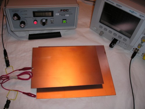
Figure 1. Experimental Setup with Parallel Plates and Connecting Wire
Abstract: Oscilloscopes are
more common in most engineering labs than network analyzers or spectrum
analyzers, so measurement methods that use oscilloscopes maximize the
return on lab equipment for many companies. A method of measuring
structural resonances using an inexpensive pulse generator and an
oscilloscope is described and results are presented.
Discussion: In the June 2006 Technical Tidbit,
I described a method of using a spectrum analyzer or a network analyzer
to measure structural resonances in electronic equipment. But what if
you don't have one of these instruments? Figure 1 shows the
test setup for an alternate method using an oscilloscope and an
inexpensive pulse generator. This setup was used to generate the data
presented in this Technical Tidbit. The test setup is composed of two copper
clad boards connected by the red test
wire and separated by about two cm to simulate two
circuit boards in proximity or a circuit board mounted over a chassis.
The wire connecting the board "ground planes," while on the long side,
is not any worst than many board to board or board to chassis ground
connections I have seen in industrial equipment and some
medical equipment.
There are two wire loops (a.k.a. magnetic field probes) placed near the red wire so that one side of each loop is parallel to the wire. One loop is connected to a pulse generator, model TG-EFT, from Fischer Custom Communications that is shown in Figure 2. The general method of using this pulse generator and magnetic loops to couple pulsed noise into circuits is described in the October 2007 Technical Tidbit on this site. The second loop is connected to a 50 Ohm input of the scope. A detailed picture showing construction details of one of the loops is shown in Figure 3.
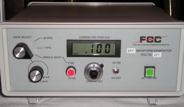
Figure 2. Fischer TG-EFT Pulse Generator
The TG-EFT pulse generator was set to 166 Volts open circuit for this test. The pulse voltage coupled into the red wire has a risetime of about 300 ps and a duration of about 4 ns. This stimulus results in ringing at the resonant frequency of the setup. In some cases, more than one resonant frequency may be present.
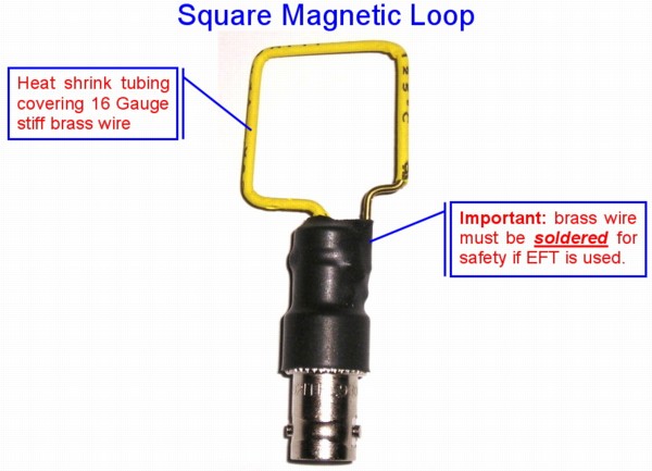
Figure 4 shows a close-up of the loops coupled to the red "grounding" wire. The mutual inductance between each loop and the wire is likely on the order of about 10 nH of the total loop self-inductance of about 80 nH. The loops are separated to minimize direct coupling between the pulse generator driven loop and the sensing loop connected to the scope. Excessive direct coupling between the loops can result in too much loop output to the scope from the initial pulse, making it difficult to see the resonance without overloading the scope input.
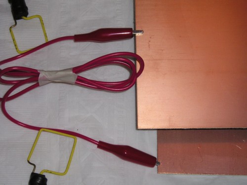
Figure 4. Close-up of Loops Coupled to Wire Connecting the two Boards
Figure 5 shows the output of the loop connected to the scope. Since I knew the resonance would be at a relatively low frequency, I used the bandwidth limit on the scope vertical amplifier to filter out the initial pulse from the generator and show only the resonance of the boards and connecting wire. The amplitude of about 20 mV is of little importance being determined by the generator output, the mutual inductance between the loops and the wire, and the vertical amplifier bandwidth limit used in the scope.
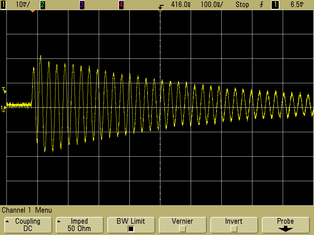
Figure 5. Resonance of Plates and Wire
In Figure 6, the first few cycles of Figure 5 are expanded to measure the ringing frequency. The scope indicates a frequency of about 37 MHz (readout near bottom of screen). A frequency in this range is to be expected given the circuit dimensions.
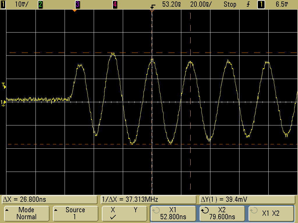
Figure 6. Frequency Measurement of Resonance, ~37 MHz
This method is especially useful for systems where boards and system components are connected by wires having resonances below 100 MHz. One could also use RF injection probes and current probes to do similar measurements on longer system cables at lower frequencies. Higher frequencies will be the topic of Part 2 of this Technical Tidbit.
There are two wire loops (a.k.a. magnetic field probes) placed near the red wire so that one side of each loop is parallel to the wire. One loop is connected to a pulse generator, model TG-EFT, from Fischer Custom Communications that is shown in Figure 2. The general method of using this pulse generator and magnetic loops to couple pulsed noise into circuits is described in the October 2007 Technical Tidbit on this site. The second loop is connected to a 50 Ohm input of the scope. A detailed picture showing construction details of one of the loops is shown in Figure 3.
Figure 2. Fischer TG-EFT Pulse Generator
The TG-EFT pulse generator was set to 166 Volts open circuit for this test. The pulse voltage coupled into the red wire has a risetime of about 300 ps and a duration of about 4 ns. This stimulus results in ringing at the resonant frequency of the setup. In some cases, more than one resonant frequency may be present.
Figure 3. Loop Used for Noise Injection
Figure 4 shows a close-up of the loops coupled to the red "grounding" wire. The mutual inductance between each loop and the wire is likely on the order of about 10 nH of the total loop self-inductance of about 80 nH. The loops are separated to minimize direct coupling between the pulse generator driven loop and the sensing loop connected to the scope. Excessive direct coupling between the loops can result in too much loop output to the scope from the initial pulse, making it difficult to see the resonance without overloading the scope input.
Figure 4. Close-up of Loops Coupled to Wire Connecting the two Boards
Figure 5 shows the output of the loop connected to the scope. Since I knew the resonance would be at a relatively low frequency, I used the bandwidth limit on the scope vertical amplifier to filter out the initial pulse from the generator and show only the resonance of the boards and connecting wire. The amplitude of about 20 mV is of little importance being determined by the generator output, the mutual inductance between the loops and the wire, and the vertical amplifier bandwidth limit used in the scope.
Figure 5. Resonance of Plates and Wire
In Figure 6, the first few cycles of Figure 5 are expanded to measure the ringing frequency. The scope indicates a frequency of about 37 MHz (readout near bottom of screen). A frequency in this range is to be expected given the circuit dimensions.
Figure 6. Frequency Measurement of Resonance, ~37 MHz
This method is especially useful for systems where boards and system components are connected by wires having resonances below 100 MHz. One could also use RF injection probes and current probes to do similar measurements on longer system cables at lower frequencies. Higher frequencies will be the topic of Part 2 of this Technical Tidbit.
Summary: A
simple method of injecting pulses into circuits for measuring
resonant frequencies is described. This method is useful for resonances
below 100 MHz. Considerations for higher resonant frequencies will be
covered in a second Technical Tidbit on this topic.
Additional articles on this website related to this topic are:
-
Signal and Noise Measurement Techniques Using
Magnetic Field Probes (~600K)
(1999 IEEE EMC Symposium paper) - August 1999: The Paperclip Magnetic Probe
- December 2000, An Easy to Build Shielded Magnetic Loop Probe
- June 2002, Using Mutual Inductance to Measure Voltage Drop in Circuits
- April 2004, Paper Clips, They're Not Just For Emissions Anymore!
- July 2004, Induced Voltages via Electric and Magnetic Fields - ESD Immunity
- April 2005, Inductive and Capacitive Coupling - Induced Current Characteristics
- June 2006, Measuring Structural Resonances
- October 2007, Using Noise Injection for Troubleshooting Circuits
If you like the information in this article and others on this website, much more information is available in my courses. Click here to see a listing of upcoming courses on design, measurement, and troubleshooting of chips, circuits, and systems.
Click here for a description of my latest seminar to be available soon titled:
EMC
Lab Techniques for Designers
(How to find EMC problems and have some confidence your system will pass EMC testing while it is still in your lab).
(How to find EMC problems and have some confidence your system will pass EMC testing while it is still in your lab).
 |
Check out my podcast containing mp3 format short tutorials, tech news and more! Just click on the microphone to see the listing
of free
audio programs. Content is added every week on technical topics so check back frequently. |
Home