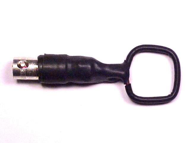
Figure 1. A Home-made Shielded Loop

Address: P. O. Box 1457, Los Gatos,
CA 95031
TEL:
800-323-3956/408-356-4186
FAX:
408-358-3799
Mobile: 408-858-4528
URL:
www.dsmith.org
Email: doug@dsmith.org
Figure 1. A Home-made Shielded Loop
Magnetic loops are useful for many measurements including: measuring voltage drop across conductors and planes, current flowing in conductors, and magnetic fields as well. Many articles on this webpage have covered uses for simple loops made from stiff wire or possibly a paper clip. Occasionally, a shielded loop is called for. One such loop is shown above in Figure 1. Usually shielded loops are made from semi-rigid coaxial cable as shown in Figure 2 below. The loop is formed by making a circle or square from the semi-rigid coax with a gap placed symmetrically in the middle of the loop. The position of the gap is very important to the performance of the shield. If the gap is not in the middle of the loop, shielding effectiveness is compromised. For more information on this property as well as more information on magnetic loops, see the paper "Signal and Noise Measurement Techniques Using Magnetic Field Probes" by clicking on the title. Square loops are very useful for making measurements of circuit voltage and current as outlined in the paper referenced above while either square or round loops are suitable for measuring magnetic fields in free space.
One problem in making a shielded probe in the lab (there is never one around when needed) is the availability of semi-rigid coaxial cable. Figures 3 through 8 show the construction steps for quickly and simply making a shielded magnetic loop in the lab.

Figure 2. Construction of Shielded Loops.
The starting material is shown in Figure 3. It is a piece of stiff copper wire or rod, 16 gauge is best for eventually fitting in the BNC connector to be used. The wire is covered with heat shrink tubing and then copper tape is wound around the heat shrink tubing so that it is covered with three layers of tape. The reason for using three layers is shown in Figure 2. When the wire is bent to form a square loop, the outermost layer may crack slightly. Such a small crack is noticeable in Figure 2. Since the crack is only on the outside of the bend and it is small, it does not pose much of a problem. But, if three layers are used, the gap will be closed by the underlying layers. This is not as much of a problem for a round loop as it is for a square loop because of the relatively sharp corners of the square loop. The characteristic impedance of the coax formed by the foil and stiff wire is probably not 50 Ohms like the feed cable likely is. But, it does not matter much since the two parasitic transmission lines formed by the two halves of the loop and their shields are unterminated at the gap in any event.
The next step is to put a second layer of heat shrink tubing over the assembly as shown in Figure 5. The loop is then bent and one end inserted into a BNC connector as shown in Figure 6. Both the other end of the wire and copper tape are soldered to the side of the BNC connector as per Figure 6. Next, the end of the BNC connector and two ends of the loop are covered in copper tape which is soldered to the copper foil of the loop as illustrated in Figure 7. The added copper tape may also be soldered to the BNC connector as well. Finally, the assembly is covered with heat shrink tubing to make the final product shown in Figure 8.
The loop's shielding may be tested as described in "Signal
and Noise Measurement Techniques Using Magnetic Field Probes" by applying
an electric field source to the loop. The loop should be least sensitive
over the gap with the maximum sensitivity just off the gap in either direction.
The sensitivity should gradually fall off as the electric field source
is moved toward the side of the loop (at the BNC connector) opposite the
gap.
 |
|
|
|
Three layers of tape used, top layer cracked. |
 |
 |
|
|
Shield and wire soldered to shell. |
 |
|
|
|
|
The performance of a loop constructed in this fashon should compare favorably with one made from semi-rigid coaxial cable up to the first resonance of the loop. The first resonance occurs at the frequency where the circumference of the loop is one half wavelength. At this frequency, the parasitic transmission lines formed by the two shields and the underlying stiff wire are one quarter wavelength unterminated stubs.