
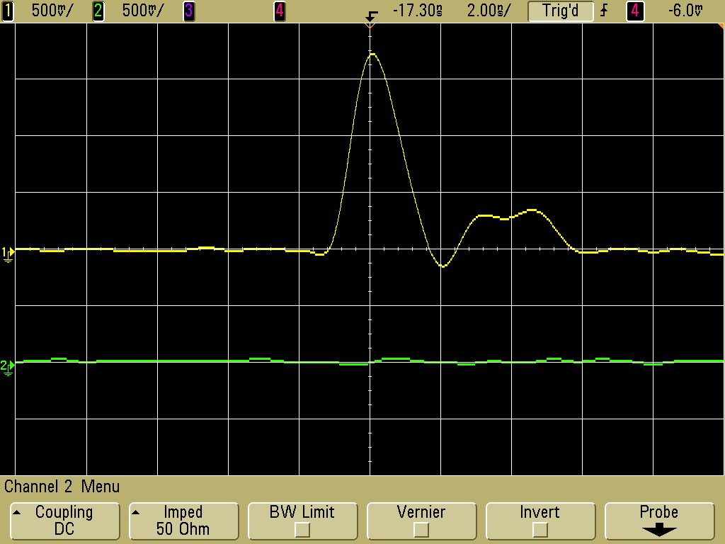
Figure 1. Pulse Injected into a Trace on a Circuit Board
(vertical scale = 500 mV/division, horizontal scale = 2 ns/div, bandwidth = 500 MHz)
Abstract: Injecting
controlled amounts of noise into a circuit can be used to find problems
in the circuit design or in the physical layout of a printed circuit
board. One method of injecting noise and two examples of available
pulse generators will be described.
Discussion: Figure 1 shows the
voltage waveform injected into a printed circuit board trace by the
method described in this article. In this case, the peak value is about
1.7 Volts with a width of a little over two nanoseconds. The amplitude
of the pulse actually injected into a circuit is a strong function of
the circuit design and the physical layout of the circuit being tested
and thus injecting noise pulses can be used to find weak points in a
design.
The method used here injects pulses via mutual inductance as a series voltage into the circuit to be tested equal to Mdi/dt of the output current of a pulse generator. The ideal pulse generator would have a current output with a fast risetime and a relatively slow falling edge. The time derivative of this current would be a single unipolar pulse, like that in Figure 1. The fast rising edge produces the injected pulse. The falling edge would normally produce a negative injected pulse, but if the falling edge is much slower than the rising edge, the negative pulse will be so small in amplitude so to be insignificant.
There are two pulse generators I know of that have a fast rising edge of output current and a slow falling edge with enough di/dt so as to produce a usable injected pulse into circuits. The first is an Electrical Fast Transient, EFT, generator that is used for the IEC 61000-4-4 immunity test. A brief description of this test can be seen on the Thermo Scientific website by clicking here.as well as an example of an EFT generator by clicking here.
In the EFT test, a 50 Ohm generator produces an output waveform with a 5 ns rise and a much slower fall time, resulting in a pulse that is about 50 ns wide at the 50% amplitude points. With a relatively slow risetime of 5 ns, a large current is needed to produce enough di/dt to inject reasonable voltages into circuits by mutual inductance. Luckily, EFT generators have outputs to at least 4400 Volts, which translates into a short circuit current of almost 90 Amperes. If you already have an EFT generator or plan to get one, it will work in the method described below. When I use this generator for noise injection, a typical output setting would be around 1000-1500 Volts. It's output is tailored to the IEC 61000-4-4 standard, but works well for noise injection. One disadvantage of EFT generators is they tend to be bulky and heavy, too heavy to carry around for field work or pack in carry-on luggage for air travel.
Another option is a small pulse generator. model TG-EFT, from Fischer Custom Communications that is shown in Figure 2. The pulse shown in Figure 1 was generated by the TG-EFT coupled into a path on a board using the loop shown in Figure 3. I use a similiar loop when an EFT generator is used as well. The loop represents a load of about 80 nH to the end of the coax cable from the pulse generator.
If a loop driven by the TG-EFT is held adjacent to a similar loop connected to a scope with a 50 Ohm input, the injected pulse delivered to the scope has about a 300 ps risetime. The waveform in Figure 1 was slowed somewhat by the 500 MHz scope used and inductance in the circuit path on the board.
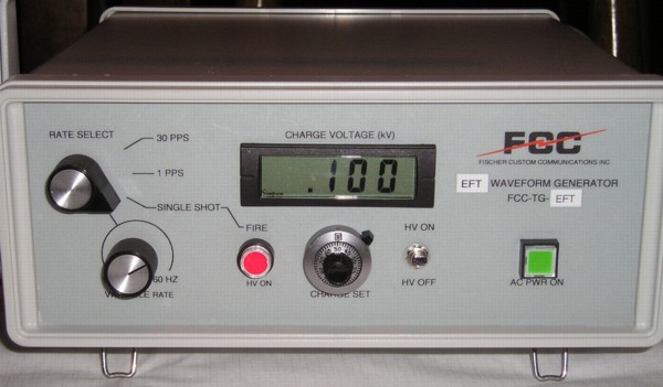
Figure 2. Fischer TG-EFT Transient Generator
The method used here injects pulses via mutual inductance as a series voltage into the circuit to be tested equal to Mdi/dt of the output current of a pulse generator. The ideal pulse generator would have a current output with a fast risetime and a relatively slow falling edge. The time derivative of this current would be a single unipolar pulse, like that in Figure 1. The fast rising edge produces the injected pulse. The falling edge would normally produce a negative injected pulse, but if the falling edge is much slower than the rising edge, the negative pulse will be so small in amplitude so to be insignificant.
There are two pulse generators I know of that have a fast rising edge of output current and a slow falling edge with enough di/dt so as to produce a usable injected pulse into circuits. The first is an Electrical Fast Transient, EFT, generator that is used for the IEC 61000-4-4 immunity test. A brief description of this test can be seen on the Thermo Scientific website by clicking here.as well as an example of an EFT generator by clicking here.
In the EFT test, a 50 Ohm generator produces an output waveform with a 5 ns rise and a much slower fall time, resulting in a pulse that is about 50 ns wide at the 50% amplitude points. With a relatively slow risetime of 5 ns, a large current is needed to produce enough di/dt to inject reasonable voltages into circuits by mutual inductance. Luckily, EFT generators have outputs to at least 4400 Volts, which translates into a short circuit current of almost 90 Amperes. If you already have an EFT generator or plan to get one, it will work in the method described below. When I use this generator for noise injection, a typical output setting would be around 1000-1500 Volts. It's output is tailored to the IEC 61000-4-4 standard, but works well for noise injection. One disadvantage of EFT generators is they tend to be bulky and heavy, too heavy to carry around for field work or pack in carry-on luggage for air travel.
Another option is a small pulse generator. model TG-EFT, from Fischer Custom Communications that is shown in Figure 2. The pulse shown in Figure 1 was generated by the TG-EFT coupled into a path on a board using the loop shown in Figure 3. I use a similiar loop when an EFT generator is used as well. The loop represents a load of about 80 nH to the end of the coax cable from the pulse generator.
If a loop driven by the TG-EFT is held adjacent to a similar loop connected to a scope with a 50 Ohm input, the injected pulse delivered to the scope has about a 300 ps risetime. The waveform in Figure 1 was slowed somewhat by the 500 MHz scope used and inductance in the circuit path on the board.
Figure 2. Fischer TG-EFT Transient Generator
With such a fast rising edge, much
less current is needed to produce the same di/dt as an EFT generator so
the TG-EFT generator is small by comparison and can be packed in
carry-on luggage on an airplane (although you may be questioned a bit
by the security people). Because of the faster edge, I tend to use an
output voltage (open circuit) of around 500 Volts or less when scanning
circuit boards, sometimes as low as 100 Volts. The TG-EFT will produce
up to a 2000 Volt pulse, although I have never had to use anywhere near
that amplitude in my investigations.
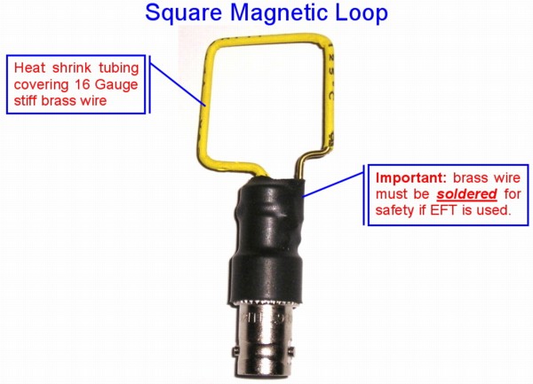
As mentioned earlier, I use a wire loop, such as the one in Figure 3, to inject the pulses into printed circuit boards, wires, and even ICs. The loop can be used to find sensitive areas of a system or board. After some experience, one can correlate the amount of noise it takes to affect the most sensitive part of the circuit to the circuit's response to environmental noise like ESD or EFT.
The TG-EFT produces positive pulses, so the drop across the top of the loop in Figure 3 will be positive to negative from left to right. The injected voltage will have the same polarity (positive left, negative right), but as a source not a drop, so the injected current will flow in the opposite direction, from right to left.
A word of caution: The ground side of the loop must be securely connected to the shield of the coax from the pulse generator. If that connection breaks, the whole loop will be at the open circuit voltage of the generator.
I have had a lot of fun injecting noise over the years, and in the process have fixed a lot of designs. I have developed this method into a very effective test procedure that is covered in detail in one of my seminars (pdf file). An interesting note about the procedure is that it is often best done by someone not involved in the design, such as a quality person testing the robustness of a design.
As mentioned earlier, I use a wire loop, such as the one in Figure 3, to inject the pulses into printed circuit boards, wires, and even ICs. The loop can be used to find sensitive areas of a system or board. After some experience, one can correlate the amount of noise it takes to affect the most sensitive part of the circuit to the circuit's response to environmental noise like ESD or EFT.
The TG-EFT produces positive pulses, so the drop across the top of the loop in Figure 3 will be positive to negative from left to right. The injected voltage will have the same polarity (positive left, negative right), but as a source not a drop, so the injected current will flow in the opposite direction, from right to left.
A word of caution: The ground side of the loop must be securely connected to the shield of the coax from the pulse generator. If that connection breaks, the whole loop will be at the open circuit voltage of the generator.
Figure 3. Loop Used for Noise Injection
I have had a lot of fun injecting noise over the years, and in the process have fixed a lot of designs. I have developed this method into a very effective test procedure that is covered in detail in one of my seminars (pdf file). An interesting note about the procedure is that it is often best done by someone not involved in the design, such as a quality person testing the robustness of a design.
Summary: A
simple method of injecting noise into circuits for troubleshooting was
described using a fast high amplitude pulse generator. This method has
been very successful in debugging circuits.
Additional articles on this website related to this topic are:
-
Signal and Noise Measurement Techniques Using
Magnetic Field Probes (~600K)
(1999 IEEE EMC Symposium paper) - August 1999: The Paperclip Magnetic Probe
- December 2000, An Easy to Build Shielded Magnetic Loop Probe
- June 2002, Using Mutual Inductance to Measure Voltage Drop in Circuits
- April 2004, Paper Clips, They're Not Just For Emissions Anymore!
- July 2004, Induced Voltages via Electric and Magnetic Fields - ESD Immunity
- April 2005, Inductive and Capacitive Coupling - Induced Current Characteristics
If you like the information in this article and others on this website, much more information is available in my courses. Click here to see a listing of upcoming courses on design, measurement, and troubleshooting of chips, circuits, and systems.
Click here for a description of my latest seminar to be available soon titled:
EMC
Lab Techniques for Designers
(How to find EMC problems and have some confidence your system will pass EMC testing while it is still in your lab).
(How to find EMC problems and have some confidence your system will pass EMC testing while it is still in your lab).
 |
Check out my podcast containing mp3 format short tutorials, tech news and more! Just click on the microphone to see the listing
of free
audio programs. Content is added every week on technical topics so check back frequently. |
Home