
Figure 1. Measuring the Resonant Frequency of a Wire Loop
Abstract: Measuring the resonant frequency of a circuit can yield information from which
circuit parameters can be determined. An example is given of using the
resonance of a small wire loop attached to a BNC barrel adapter to
calculate the capacitance of the adapter. This method can be applied to
connectors and other structures as well and is especially useful if a
network analyzer is not available.
Discussion: This Technical
Tidbit details an example of using the resonant frequency of a circuit
to determine a desired circuit parameter, in this case the capacitance
of a BNC barrel adapter. I have used measurements and caclulations like
this many times to derive circuit parameters where I did not have
access to a network analyzer. In some of the earlier cases, I am not
sure network analyzers were available at all.
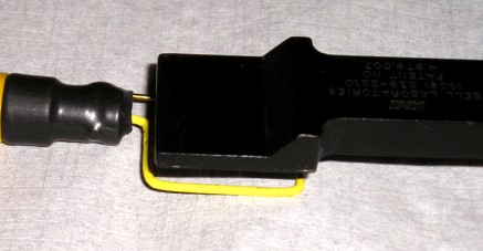
Figure 1 shows the experimental setup composed of a one inch (~2.5 cm) square wire loop connected to a BNC barrel adapter, covered with yellow heat shrink tubing, and a black plastic covered square shielded loop of the same size held over the plain wire loop. One way of constructing a square shielded loop is given in my December 2000 Technical Tidbit. Figure 2 shows a picture of the wire loop and BNC barrel adapter. Sometimes I feed the loop high voltage electrical transient waveforms, as in the November 2007 Technical Tidbit. For those applications, soldering the wire to the BNC barrel is important for safety. For the method of this article, soldering the wire is not critical but leads to a physically robust loop. The 16 AWG brass wire used to form the loop is stiff enough to hold its shape, is easy to solder, and just fits into the center pin hole of the BNC adapter.
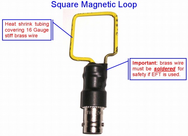
Figure 2. Wire Loop Construction
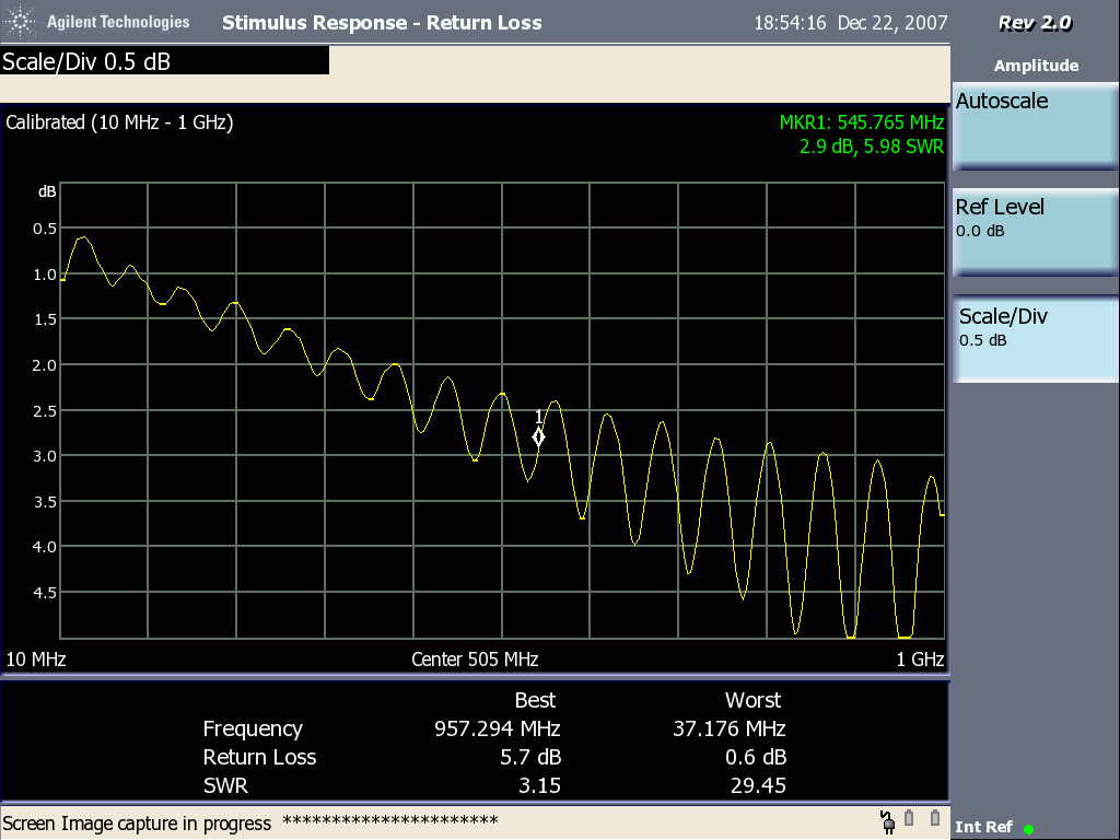
The black plastic covered square shielded loop is driven from the tracking generator of a spectrum analyzer and its return loss relative to 50 Ohms plotted in Figure 3. One could also plot SWR or reflection coefficient and get a similar result. The June 2006 Techical Tidbit describes how to optimize the measurement parameters of the instrument. A directional coupler can also be used to measure the reflected power from the loop if the instrument cannot directly measure it. For this test, a shielded loop is preferred for connection to the tracking generator signal source to minimize errors caused by capacitance between the loop and the structure to be measured.
In Figure 3, note the sharp dip of about 2 to 3 dB in the return loss of the shielded loop at about 363 MHz. At that frequency, the inductance of the wire loop and the capacitance of the BNC barrel adapter is resonant and the resulting tuned circuit absorbs energy from the shielded loop above it. The result is the dip evident in Figure 3.
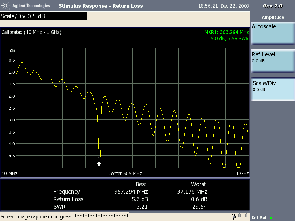
Figure 3. Return Loss vs. Frequency Plot Showing a Resonance at ~363 MHz
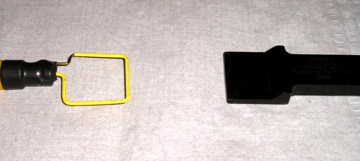
That the dip in Figure 3 is due to the wire loop and its BNC barrel adapter forming a resonant circuit can be shown by Figures 4 and 5. Figure 4 shows the two loops separated by a distance greater than the size of the loops and Figure 5 shows the resulting return loss plot. As can be seen in Figure 5, there is no dip at 363 MHz., just the small series of ripples in the return loss. The gradual downward trend in Figure 5 of increasing return loss as frequency increases is mostly due to loss in the RG174 coax cable used to connect the shielded loop to the analyzer.
Using the inductance calculator
at Missouri University of Science and Technology, one can determine the
inductance of the yellow wire loop as being about 80 nh. Since the
frequency of an LC resonant tank circuit is given by:
and we know FR = 363 MHz. and L = 80 nH, the capacitance of the circuit (which is mostly in the BNC barrel adapter) must be about 2.4 pF. I have used techniques like this to develop electrical models of connectors and other physical structures when a network analyzer was not available.
Figure 1 shows the experimental setup composed of a one inch (~2.5 cm) square wire loop connected to a BNC barrel adapter, covered with yellow heat shrink tubing, and a black plastic covered square shielded loop of the same size held over the plain wire loop. One way of constructing a square shielded loop is given in my December 2000 Technical Tidbit. Figure 2 shows a picture of the wire loop and BNC barrel adapter. Sometimes I feed the loop high voltage electrical transient waveforms, as in the November 2007 Technical Tidbit. For those applications, soldering the wire to the BNC barrel is important for safety. For the method of this article, soldering the wire is not critical but leads to a physically robust loop. The 16 AWG brass wire used to form the loop is stiff enough to hold its shape, is easy to solder, and just fits into the center pin hole of the BNC adapter.
Figure 2. Wire Loop Construction
The black plastic covered square shielded loop is driven from the tracking generator of a spectrum analyzer and its return loss relative to 50 Ohms plotted in Figure 3. One could also plot SWR or reflection coefficient and get a similar result. The June 2006 Techical Tidbit describes how to optimize the measurement parameters of the instrument. A directional coupler can also be used to measure the reflected power from the loop if the instrument cannot directly measure it. For this test, a shielded loop is preferred for connection to the tracking generator signal source to minimize errors caused by capacitance between the loop and the structure to be measured.
In Figure 3, note the sharp dip of about 2 to 3 dB in the return loss of the shielded loop at about 363 MHz. At that frequency, the inductance of the wire loop and the capacitance of the BNC barrel adapter is resonant and the resulting tuned circuit absorbs energy from the shielded loop above it. The result is the dip evident in Figure 3.
Figure 3. Return Loss vs. Frequency Plot Showing a Resonance at ~363 MHz
That the dip in Figure 3 is due to the wire loop and its BNC barrel adapter forming a resonant circuit can be shown by Figures 4 and 5. Figure 4 shows the two loops separated by a distance greater than the size of the loops and Figure 5 shows the resulting return loss plot. As can be seen in Figure 5, there is no dip at 363 MHz., just the small series of ripples in the return loss. The gradual downward trend in Figure 5 of increasing return loss as frequency increases is mostly due to loss in the RG174 coax cable used to connect the shielded loop to the analyzer.
Figure 4. Separating the Wire Loop Being Measured from the Energized Shielded Loop
Figure 5. Return Loss of Shielded Loop Separated from the Wire Loop
and we know FR = 363 MHz. and L = 80 nH, the capacitance of the circuit (which is mostly in the BNC barrel adapter) must be about 2.4 pF. I have used techniques like this to develop electrical models of connectors and other physical structures when a network analyzer was not available.
Summary: A
technique was shown for measuring the resonant frequency of a circuit
and then using this to calculate the capacitance of a BNC barrel
adapter. The technique can be extended to analyze a wide variety of
circuits.
Additional articles on this website related to this topic are:
- December 2000, An Easy to Build Shielded Magnetic Loop Probe
- June 2006, Measuring Structural Resonances
- November 2007, Measuring Structural Resonances in the Time Domain - Part 1
- Missouri University of Science and Technology inductance calculator
- Scott Roleson's original article in the January 1998 issue of Medical Device & Diagnostic Industry Magazine
on measuring structural resonances
- The spectrum analyzer used is an Agilent N1996A.
Click here for a description of my latest seminar titled:
EMC
Lab Techniques for Designers
(How to find EMC problems and have some confidence your system will pass EMC testing while it is still in your lab).
(How to find EMC problems and have some confidence your system will pass EMC testing while it is still in your lab).
 |
Check
out my podcast containing mp3 format short tutorials, tech news and
more! Just click on the
microphone to see the listing
of free
audio programs. Content is added every week on technical
topics so check back frequently. |
Home