
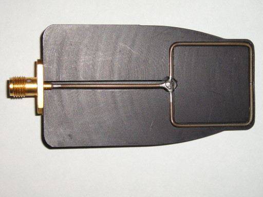
Figure 1. Cutaway View of a Square Shielded Loop
Abstract: Square magnetic
loops are very useful troubleshooting tools and are used in some of the
articles on this website. This is the first in a series of articles
describing the construction and characteristics of shielded magnetic
loops as well as comparing them to unshielded magnetic loops made from
stiff wire. The construction of a square
shielded loop is described.
Discussion: Figure 1 shows a
square shielded loop built into a plastic housing which has been split
to show the loop inside. The electrical construction of the loop is
described in my 1999 IEEE EMC Symposium paper "Signal and Noise Measurement Techniques Using
Magnetic Field Probes,"
a 600K pdf file. For our purposes, one can think of the loop as
starting with a straight length of semi-rigid coax of small diameter with an SMA
connector on one end and shorting the center conductor to the shield
with solder at the other end. Then the loop is bent around to form a
square (being careful not to bend the coax too sharply at the corners)
and the solder shorted end is soldered back on the coax so as to form a
square symmetric loop. A small gap is made in the shield in the middle
of the side opposite the feed line. A close up of the loop in Figure 1
is shown in Figure 2.
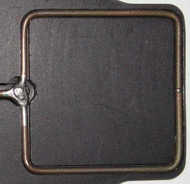
Figure 2. Close-up of Square Shielded Loop
The gap in the shield can be seen in the middle of the right side of the loop. As shown in the IEEE paper referenced above and at the end of this article, shielding against electric fields is best achieved if the field is symmetric around a line from the solder junction to the gap in the shield, a condition that is met when a shielded loop is used to measure a field much further from a source than the size of the source itself. To help insure electric field symmetry when the loop is used on the surface of a circuit board in the near field, the gapped side should be held against the board with the loop itself perpendicular to the board. And therein lies the main reason for using a square loop, most circuit boards are flat and one side of the loop can be held directly against a circuit board resulting in better coupling to the circuit than a round loop of the same size would give. More technical details are given in the IEEE paper.
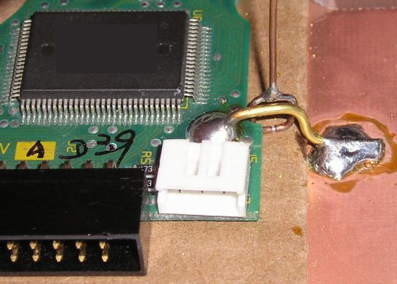
Figure 3, from the June 2006 Technical Tidbit, "Measuring Structural Resonances," shows a small square shielded loop held next to a connection between a circuit board and the underlying "chassis." In this case, there is coupling from all four sides of the loop into the circuit to achieve maximum coupling.
One can minimize the work required to build a shielded loop by buying a short length of small semi-rigid coaxial cable with SMA connectors already mounted on each end. The assembly can be cut in half to make two shielded loops saving the trouble of mounting the connectors on the semi-rigid cable. Pasternack Enterprises, http://pasternack.com, is one source of such assemblies. Look up the small diameter semi-rigid cable you want to use first on the Pasternack website and then use their cable wizard to build up the assembly you want by adding the connectors. The smaller the semi-rigid coax diameter, the better coupling between the center conductor of the coax and the adjacent circuit.
I use square shielded loops both to measure many kinds of signals and to inject small RF signals (~0 dBm) into circuits. Some of my techniques involve coupling high voltage/current short pulses into a circuit such as in the November 2007 Technical Tidbit, Measuring Structural Resonances in the Time Domain - Part 1. I do not recommend shielded loops made from small semi-rigid coax for this purpose because of possible voltage breakdown in the coax and even heating under some conditions. For large pulses, I use unshielded stiff wire loops.
Part 2 of this series will present measurements of small RF signals injected by a square shielded loop contrasted to the result using just a stiff wire loop in the frequency domain.
Figure 2. Close-up of Square Shielded Loop
The gap in the shield can be seen in the middle of the right side of the loop. As shown in the IEEE paper referenced above and at the end of this article, shielding against electric fields is best achieved if the field is symmetric around a line from the solder junction to the gap in the shield, a condition that is met when a shielded loop is used to measure a field much further from a source than the size of the source itself. To help insure electric field symmetry when the loop is used on the surface of a circuit board in the near field, the gapped side should be held against the board with the loop itself perpendicular to the board. And therein lies the main reason for using a square loop, most circuit boards are flat and one side of the loop can be held directly against a circuit board resulting in better coupling to the circuit than a round loop of the same size would give. More technical details are given in the IEEE paper.
Figure 3, from the June 2006 Technical Tidbit, "Measuring Structural Resonances," shows a small square shielded loop held next to a connection between a circuit board and the underlying "chassis." In this case, there is coupling from all four sides of the loop into the circuit to achieve maximum coupling.
Figure 3. Example of a Small Shielded Loop
One can minimize the work required to build a shielded loop by buying a short length of small semi-rigid coaxial cable with SMA connectors already mounted on each end. The assembly can be cut in half to make two shielded loops saving the trouble of mounting the connectors on the semi-rigid cable. Pasternack Enterprises, http://pasternack.com, is one source of such assemblies. Look up the small diameter semi-rigid cable you want to use first on the Pasternack website and then use their cable wizard to build up the assembly you want by adding the connectors. The smaller the semi-rigid coax diameter, the better coupling between the center conductor of the coax and the adjacent circuit.
I use square shielded loops both to measure many kinds of signals and to inject small RF signals (~0 dBm) into circuits. Some of my techniques involve coupling high voltage/current short pulses into a circuit such as in the November 2007 Technical Tidbit, Measuring Structural Resonances in the Time Domain - Part 1. I do not recommend shielded loops made from small semi-rigid coax for this purpose because of possible voltage breakdown in the coax and even heating under some conditions. For large pulses, I use unshielded stiff wire loops.
Part 2 of this series will present measurements of small RF signals injected by a square shielded loop contrasted to the result using just a stiff wire loop in the frequency domain.
Summary: The
construction details of a square shielded loop were presented along
with a source of materials for building one. Square shielded loops are
very useful devices which will be explored in the next part of this
series.
Additional articles on this website related to this topic are:
- Signal and Noise Measurement Techniques Using Magnetic Field Probes (~600K)
- (1999 IEEE EMC Symposium paper)
- December 2000, An Easy to Build Shielded Magnetic Loop Probe
- June 2006, Measuring Structural Resonances
- November 2007, Measuring Structural Resonances in the Time Domain - Part 1
- February 2008, Using Resonant Frequency Measurements to Extract Circuit Parameters
(Calculating the Capacitance of a BNC Barrel Adapter) - April 2008, Measuring Structural Resonances - Part 2, Printed Wiring Board Traces
(A Simple Technique for Determining the Resonant Frequencies of a PWB Trace)
Click here for a description of my latest seminar titled:
EMC
Lab Techniques for Designers
(How to find EMC problems and have some confidence your system will pass EMC testing while it is still in your lab).
(How to find EMC problems and have some confidence your system will pass EMC testing while it is still in your lab).
 |
Check
out my podcast containing mp3 format short tutorials, tech news and
more! Just click on the
microphone to see the listing
of free
audio programs. Content is added every week on technical
topics so check back frequently. |
Home