
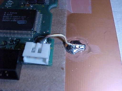
Figure 1. PCB With Chassis Ground Connection
Abstract: PCB to chassis
ground connections are often needed in electronic equipment, but if
care is not taken, the PCB and the chassis ground structure can become
a hi-Q resonant circuit that may cause problems. Background information
is given and techniques to avoid problems in designs are discussed.
Discussion: Connecting PCB
signal grounds to equipment chassis ground is a common feature in
electronic systems although not necessarily done as shown for the
experimental board in Figure 1. Problems can arise when the PCB and
nearby metal, whether it is another PCB or chassis metal, form a
parallel plate capacitor and the connections between them form an
inductor. The combination forms a high-Q resonant circuit as
illustrated in Figure 2. If this resonant circuit is tuned to a clock
harmonic or other critical system frequeny, there is a risk of an EMC problem or even an
operational problem for sensitive circuits. At today's frequencies, all PCBs have significant
capacitance to nearby metal and all connecting wires are inductors.
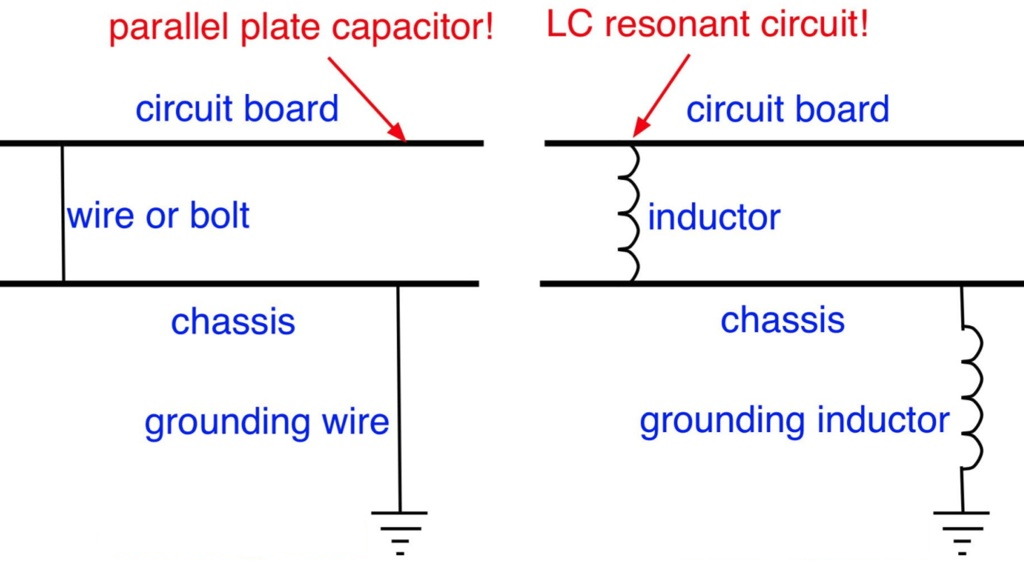
Figure 2. Equivalent Circuit of PCB and Chassis Connections
There are two ways to approach this potential problem.
Figure 2. Equivalent Circuit of PCB and Chassis Connections
There are two ways to approach this potential problem.
- Measure the resonant frequencies of the PCB/chassis or other PCB structure and adjust the number of ground connections to move the resonant frequency of the structure away from critical system frequencies. See June 2006, Technical Tidbit: Measuring Structural Resonances.
- Leave the option to put a small resistor in one or a few of the ground connections (but not all) to dampen the resonance that occurs. Usually the value of this resistor is on the order of 20 Ohms. The optimum value is equal to the reactance of the PCB to metal capacitance at resonance. For further information see February 2010, Damping Board Resonances Using Discrete Resistors and March 2010, Damping Board Resonances Using Discrete Resistors - Part 2.
Summary: Don't
take chances with your design, engineer the system resonances involving
PCBs rather than letting system performance fall to chance.
Additional articles on this website related to this topic are:
- April 2002 Technical Tidbit: Printed Wiring Board Coupling to a Nearby Metal Plane
- June 2006, Technical Tidbit: Measuring Structural Resonances
- March 2007, Technical Tidbit: Isolating Board and Chassis Grounds - A Potential Problem
(An ESD Example) - February 2010, Damping Board Resonances Using Discrete Resistors
- March 2010, Damping Board Resonances Using Discrete Resistors - Part 2
Need help with a design or additional training on technical subjects? Click on the image below to go to CircuitAdvisor.com, a new engineering resource for training, news, and fun.

If you like the information in this article and others on this website,
much more information is available in my courses. Click here
to see a listing of upcoming courses on design, measurement, and
troubleshooting of chips, circuits, and systems. Click here to see upcoming seminars in Newport Beach, CA.
Click here for a description of my latest seminar titled (now also available online as a WebEx seminar):
EMC
Lab Techniques for Designers
(How to find EMC problems and have some confidence your system will pass EMC testing while it is still in your lab).
(How to find EMC problems and have some confidence your system will pass EMC testing while it is still in your lab).
Home