Printed Wiring Board Coupling to a Nearby Metal Plane
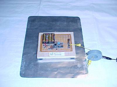
Figure 1. Test Setup to Measure Coupling to Metal Plane

Address: P. O. Box 1457, Los Gatos,
CA 95031
TEL:
800-323-3956/408-356-4186
FAX:
408-358-3799
Mobile: 408-858-4528
URL:
www.dsmith.org
Email: doug@dsmith.org
Figure 1. Test Setup to Measure Coupling to Metal Plane
Many electronic products have a circuit board in close proximity to a metal plane, usually part of an enclosure. In a shelf of printed wiring boards, an adjacent board can act like a nearby metal plane. The coupling between a printed wiring board and a nearby metal plane can be surprisingly strong. The coupling can be so strong that it is not possible to implement a "single point ground" between the board and the plane. In the case of adjacent boards in a shelf, significant currents can be created in the boards and the interconnecting backplane.
The test setup for this experiment is shown in Figure 1 above. The 5 Volt squarewave output of an HC240 gate was connected through a 15 cm wire to a ground plane and the current in the wire was measured by a current probe for two conditions. In the first condition, the oscillator is placed off of the plane and as far from the metal plane as the interconnecting wire would allow. In the second configuration, shown in Figure 1, the oscillator is placed over the metal plane. The ground plane of the oscillator circuit board (about 6 by 15 cm) was about 1.5 cm above the metal ground plane, somewhat further than the separation found in many products.
Figure 2 below shows the current in the connecting wire for the first condition, the oscillator is as far off the plane as the wire will allow. About 10 mA peak is flowing in the wire at just under 30 MHz. This is due to the small capacitance between the plate and oscillator as well as as free space capacitance. However, look what happens when the oscillator is moved onto the plate as shown in Figure 1. Figure 3 shows the resulting current at an oscillator frequency that is the same as used for Figure 2, just under 30 MHz.
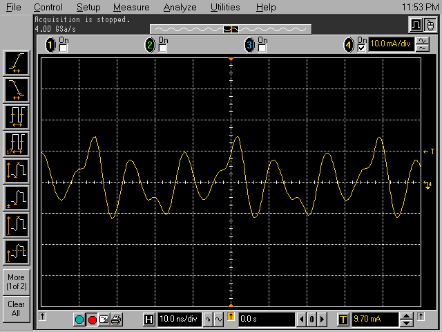
Figure 2. Current in Wire Connecting Output of Oscillator to Plane
(oscillator off plane)
The current has increased to nearly 40 mA peak! The trace looks much
like a modulated sine wave because the inductance of the wire forms a tuned
circuit with the capacitance between the oscillator and metal plane. The
ringing frequency is about 77 MHz, the third harmonic of the oscillator,
running near 26 MHz. The highest positive and negative peaks correspond
to the positive and negative going edges of the fundamental frequency of
the squarewave from the oscillator which was tuned to get the resonant
condition seen in Figure 3. If this oscillator could run at 77 MHz, the
result would likely be a higher peak current.
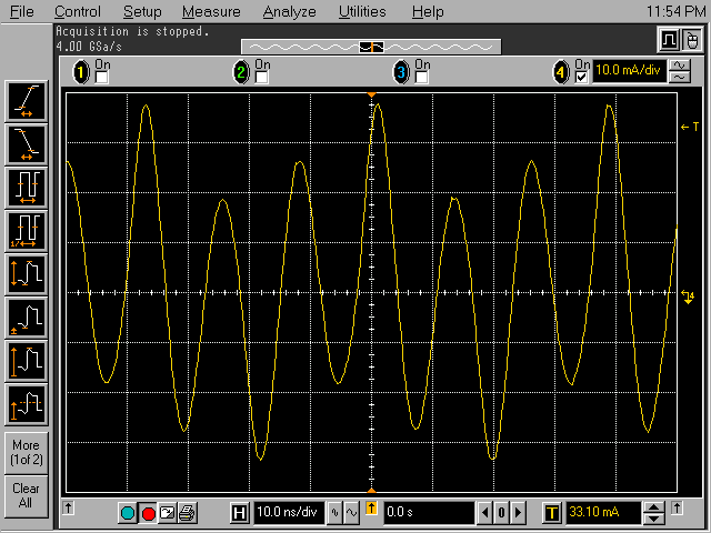
Figure 3. Current in Wire Connecting Output of Oscillator to Plane
(oscillator on plane as shown in Figure 1)
The important point is the 40 mA peak current. That is enough current to require lots of shielding by the enclosure and system cables (likely 40 to 60 dB) to avoid emissions problems. Even the current in Figure 2, measured in milliamps not microamps, is enough to be a potential problem. The driving voltage is the 5 volt output of the oscillator and one might say their board does not have that much ground noise to drive such currents. That is true, but we are talking about tens of milliamps of current in this example. Just a few hundred millivolts of noise will be able to drive plenty of current to cause problems if that current can get outside of the system either through openings in the enclosure or on cables. Sometimes a current such as this flowing inside a chassis creates a voltage drop across an impedance, a seam for example, and then that voltage causes an EMC problem by driving a current that flows outside the enclosure.
Many systems that mount a circuit board to a nearby metal plane use short metal stand-off mounts. Use of these mounts to connect the board ground to the plane will raise the resonant frequency of the configuration. However, many circuits use much higher frequencies than used in this experiment so there may still be a problem if only one chassis connection is made as in the experiment above. The situation can often be made better by multiple connections between a board and a nearby metal plane. The analysis of such a configuration is beyond the scope of this short article and problems can result if the grounding points are not carefully selected. If an attempt is made to isolate the board from the plane, no deliberate connection, the current will then flow through parasitic coupling. The difference is that the designer is not controlling where the currents flow and problems may result.
The bottom line is that the two ground planes (board and metal plate) are strongly coupled and that this coupling can result in large currents flowing on boards, nearby metal, and the connecting structures. This current can cause significant emissions problems (and by reciprocity immunity problems as well). There is no way to achieve "single point grounding" under such circumstances. To minimize emissions, one must design the board and enclosure to get these currents back to their source on the board in the most compact way (minimum loop size) through the minimum impedance.
Other articles on this website containing information on current probes or the effects of metal planes include: