
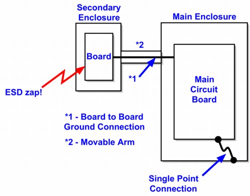
Figure 1. A System with Single Point Connection of Board "Ground" to the Chassis
Abstract: System designers
sometimes try to achieve a single point of connection between circuit
ground on printed wiring boards (PWBs) and the metal chassis of a
system for a variety of reasons. Trying to isolate grounds in this way can cause significant
immunity problems to stimuli like ESD and RF fields. Single and multiple point
grounding arrangements will be discussed.
Discussion: Figure 1 shows a
system with a main circuit board that is connected (some say
"grounded") to the enclosure or chassis at a single point. In addition,
in this example, there is a second circuit board also isolated from the
chassis in a secondary enclosure. This second board could be, for
example, a keyboard or a monitor. This grounding structure is
popular in industrial and medical products.
Sometimes the circuit boards are floated with respect to the chassis so as to prevent leakage currents, especially in medical equipment. In this case, even the single point of connection to the chassis is removed, usually replaced by a large value resistor of several megohms. But doing this is often not necessary for isolation purposes in medical equipment. Isolation is often dependent on a barrier on the main circuit board in the form of a transformer or optically isolated device. The presence of the barrier means that the circuit boards do not themselves need to be isolated from the chassis.
Single point "grounding" of circuit boards as in Figure 1 is occasionally done in an attempt to control external noise currents such as ESD from flowing through the circuit cards, but in reality the opposite often happens. As a number of the articles on this website show, trying to connect circuit boards to the chassis at only one point can cause resonances and other problems. A few of the most relevant Technical Tidbit articles are listed at the bottom of this page.
In Figure 1, if ESD is applied to the circuit board in the secondary enclosure, the low frequency current of the ESD event must flow though both circuit boards before reaching the chassis. Directing ESD currents through circuit boards is not a good idea. At higher frequencies, tens of MHz and higher, the capacitance of the boards to the chassis and the inductance of the board connections to each other and to the chassis will form resonant circuits and result in oscillatory currents flowing in the circuit boards and their connection to the chassis. Figure 2 shows just such an oscillatory response described in the May 2002 Technical Tidbit on this site for a board mounted over a metal chassis connected at a single point and ESD is applied to the metal chassis. Again, this is not a good situation from an immunity standpoint.
Figure 2. Voltage Drop Across a Short "Single Point Ground" Connection of a Circuit Board to a Metal Plane
(actual vertical scale is about 3 Volts/div)
Adding more ground points can raise the resonant frequencies, lower current amplitudes, and divert ESD currents to the chassis instead of forcing them through other system components including boards. Once in a while, a specific ground connection (out of many) can cause a problem. Such a problem should be analyzed by current measurements and fixed if it occurs. I have found such problems to be rare compared to those caused by attempting a single point ground.
Occasionally, a circuit board really needs to be connected to the chassis at only one point. Such situations are not common and if one is thinking of doing this, a solid justification based upon measurements is needed, not just intuition or "this is the way we have always done it." If ESD or EMI problems result they will need to be addressed early in the system design cycle as major changes may be needed.
Other articles on this website related to this topic are:
- April 2002, Printed Wiring Board Coupling to a Nearby Metal Plane
- May 2002, Printed Wiring Board Coupling to a Nearby Metal Plane, Part 2: ESD Immunity
- October 2002, Printed Wiring Board Coupling to a Nearby Metal Plane, Part 3: System Measurements
Click here for a description of my latest seminar to be available soon titled:
EMC
Lab Techniques for Designers
(How to find EMC problems and have some confidence your system will pass EMC testing while it is still in your lab).
(How to find EMC problems and have some confidence your system will pass EMC testing while it is still in your lab).
 |
Check out my podcast containing mp3 format short tutorials, tech news and more! Just click on the microphone to see the listing
of free
audio programs. Content is added every week on technical topics so check back frequently. |
Home