
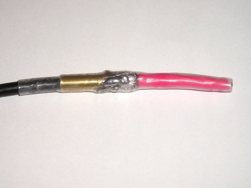
Figure 1. Completed 1.85 GHz Coaxial Dipole Antenna
Abstract: A small coaxial antenna
built at the end of a coaxial cable can be useful for troubleshooting
circuits and equipment for sensitivity to near field mobile phone
emissions. A practical implementation of such an
antenna is presented. The resulting antenna is rugged and easy to use.
Discussion: In the February 2006 Technical Tidbit titled "Construction of a Coaxial Antenna for Troubleshooting"
the theory of operation, construction details, and use of a coaxial
antenna built on the end of a coaxial cable are discussed. Since then I
have had a need to build a few of these antennas and worked out an
improved construction technique.
Figure 1 shows a close-up picture of one of these antennas cut to resonate at 1850 MHz. Instead of just folding the shield back over the cable jacket to form one half of a dipole antenna, I slipped a small brass tube over the end of the coaxial cable and soldered the shield around the end of the tube. The tube should be sized so as to be a close fit to the jacket of the coaxial cable. The use of the brass tubing makes the antenna more rugged and helps the antenna maintain its shape. The center conductor is extended just as in the February 2006 article and covered with a few layers of heat shrink tubing (the red tubing in Figure 1) so that a final piece of heat shrink tubing will fit snuggly over the entire antenna (the clear tubing in Figure 1).
The resulting antenna is easy to use and will stand up to rugged lab use. The brass tube and extended center conductor are both 3 cm in length in Figure 1, resulting in a dipole tuned to about 1850 MHz. When building one of these antennas, only a little extra work is needed to build a second one since two pieces of brass tubing can be cut at the same time. Figure 2 shows the pair I built one evening. The heat shrink tubing on the lower antenna is a little longer, but the two antennas are electrically identical.
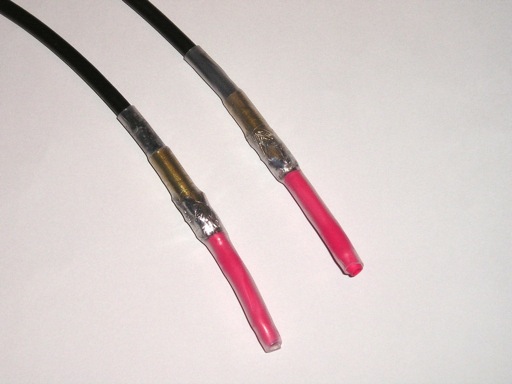
Figure 2. Pair of 1.85 GHz Coaxial Dipole Antenns
Summary: An
improved construction technique is described for a small coaxial
antenna that is useful in near field immunity testing for possible
mobile phone caused problems in equipment. The resulting antenna is
rugged and easy to use.
Additional articles on this website related to this topic are:
Need help with a design or additional training on technical subjects? Click on the image below to go to CircuitAdvisor.com, a new engineering resource for training, news, and fun.

If you like the information in this article and others on this website,
much more information is available in my courses. Click here
to see a listing of upcoming courses on design, measurement, and
troubleshooting of chips, circuits, and systems. Click here to see upcoming seminars in Newport Beach, CA.
Click here for a description of my latest seminar titled (now also available online as a WebEx seminar):
EMC
Lab Techniques for Designers
(How to find EMC problems and have some confidence your system will pass EMC testing while it is still in your lab).
(How to find EMC problems and have some confidence your system will pass EMC testing while it is still in your lab).
Home