
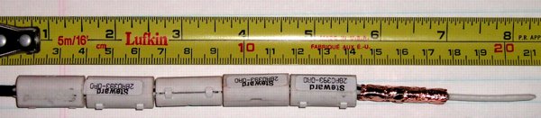
Figure 1. 1.8 GHz Antenna Made From Coax
Abstract: A simple antenna is
described that is easily made from coaxial cable and is useful for
troubleshooting purposes. It is balanced and does not require a
balun to be fed from coaxial cable. Such an antenna has many uses
around the lab.
Discussion: A simple dipole antenna can be made from the stripped end of coaxial cable. This type of antenna is used in some wireless products and can be used to expose equipment to simulated fields from wireless devices. Figure 1 shows an example of such an antenna. It is made by stripping the cable to expose a quarter of a wavelength of center conductor while a quarter wavelength of the shield is folded back over outer covering of the coax cable.
To understand how the antenna works, Figure 2 shows the details of the antenna. In Figure 2, the shield is folded back over itself for a quarter of a wavelength. The folded shield is insulated from the original shield underneath by the outer jacket of the coax. This is done in practice by taking a pointed object, such a small bladed screwdriver, and unbraiding the exposed shield so that it is composed of parallel wires. The wires are then folded back as shown in Figure 2 of my September 2004 Technical Tidbit, Mobile Phone Response to EMI from Small Metal ESD. The antenna in Figure 1 has been improved by wrapping the shield wires with copper foil tape to insure a continuous surface.
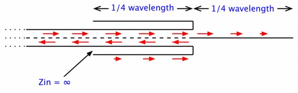
Figure 2. Drawing of Coaxial Antenna Showing Current Flow
The red arrows in Figure 2 show the direction of the currents that flow. Inside of the coax, the center conductor current is matched by an equal current returning on the inside surface of the shield. For convenience, I have shown the shield current as a single line of arrows inside of the shield. In fact, the current is spread equally over the inside surface of the shield. When the currents reach the end of the shield, the center conductor current continues out onto the exposed center conductor. Since the exposed center conductor is one quarter of a wavelength long, a standing wave exists on it causing a maximum of current as the center conductor exits the shield and zero current at its end.
The shield current folds back and flows on the outside of the copper foil covering the shield wires. Note that this current is flowing in the opposite direction as the current on the inside surface of the original coax shield.
Here's where it gets interesting. Skin effect causes the two surfaces of a thin metal sheet, such as a cable shield, to be quite independent at high frequencies as far as current flow is concerned. The outside surface of the shield of the original cable forms a "center conductor" with respect to the inside of the folded back shield with its copper foil covering. This parasitic coax is one quarter of a wavelength long and is shorted at the end where the center conductor exits. This makes the impedance looking into the other end where the folded shield stops nearly infinite. Thus as far as the current flowing on the outside of the folded shield is concerned, there is no inside surface of the folded shield at all! The impedance looking in there is nearly infinite, so the folded shield ends appearing to have no inner surface and thus the folded shield has the same standing wave on it as does the extended center conductor. The current on the folded shield is maximum at the folded end and zero at the other end. It does not enter the parasitic coax formed by the original cable shield and the inside surface of the folded back shield.
If the antenna is precisely cut there will be no common mode current flowing back on the outside of the cable towards the source. Just to be safe, the cable in Figure 1 has several ferrite cores placed on it. This allows for some error in cutting the length of the folded back shield.
The antenna in Figure 1 was cut for the upper mobile phone band, around 1800 MHz. As shown in Figure 1, it is a little longer than needed (it is easier to trim an antenna shorter than to make it longer). To calculate one quarter wavelength divide 300 by the frequency in MHz and multiply the result by 1/4. The result is then multiplied by 0.8. This is an estimated factor because wave travels slower on the cable than in free space. The antenna is then trimmed to the exact length by measuring its reflected power at the frequency of interest. When properly tuned, the reflected power will be minimized.
One can use this antenna to subject a device to the expected field of a wireless device such as a mobile phone. Just feed the antenna the correct power level (600 mW for a mobile phone at its maximum transmit power). The input impedance of this antenna is close to 70 Ohms at resonance so if 50 Ohm cable is used, allow for the mismatch reducing the actual transmitted power. Holding this antenna close to another device will show if a nearby mobile phone will cause problems. For the specific case of mobile phones, one antenna will need to be made for each frequency band to be tested.
A few final cautions are in order. If you are using an antenna like the one described in this article for troubleshooting radiated immunity problems, be careful not to cause interference or use so much power as to be dangerous. Performing the test in a shielded chamber is desirable. When I am troubleshooting with this antenna, it is usually done at very close ranges to simulate proximity to a mobile phone. An anechoic chamber may not be needed for this case since the path length for reflections off the walls is so much greater than the few centimeter or less distance between the antenna to the product. A plain shielded chamber may be adequate.
Don't forget safety! Power levels above WiFi and mobile phone levels can be dangerous under some conditions.
Summary: A simple antenna can be made from coaxial cable. This antenna is useful in subjecting electronic devices to simulated radiation from a nearby wireless device such as a mobile phone.
Discussion: A simple dipole antenna can be made from the stripped end of coaxial cable. This type of antenna is used in some wireless products and can be used to expose equipment to simulated fields from wireless devices. Figure 1 shows an example of such an antenna. It is made by stripping the cable to expose a quarter of a wavelength of center conductor while a quarter wavelength of the shield is folded back over outer covering of the coax cable.
To understand how the antenna works, Figure 2 shows the details of the antenna. In Figure 2, the shield is folded back over itself for a quarter of a wavelength. The folded shield is insulated from the original shield underneath by the outer jacket of the coax. This is done in practice by taking a pointed object, such a small bladed screwdriver, and unbraiding the exposed shield so that it is composed of parallel wires. The wires are then folded back as shown in Figure 2 of my September 2004 Technical Tidbit, Mobile Phone Response to EMI from Small Metal ESD. The antenna in Figure 1 has been improved by wrapping the shield wires with copper foil tape to insure a continuous surface.
Figure 2. Drawing of Coaxial Antenna Showing Current Flow
The red arrows in Figure 2 show the direction of the currents that flow. Inside of the coax, the center conductor current is matched by an equal current returning on the inside surface of the shield. For convenience, I have shown the shield current as a single line of arrows inside of the shield. In fact, the current is spread equally over the inside surface of the shield. When the currents reach the end of the shield, the center conductor current continues out onto the exposed center conductor. Since the exposed center conductor is one quarter of a wavelength long, a standing wave exists on it causing a maximum of current as the center conductor exits the shield and zero current at its end.
The shield current folds back and flows on the outside of the copper foil covering the shield wires. Note that this current is flowing in the opposite direction as the current on the inside surface of the original coax shield.
Here's where it gets interesting. Skin effect causes the two surfaces of a thin metal sheet, such as a cable shield, to be quite independent at high frequencies as far as current flow is concerned. The outside surface of the shield of the original cable forms a "center conductor" with respect to the inside of the folded back shield with its copper foil covering. This parasitic coax is one quarter of a wavelength long and is shorted at the end where the center conductor exits. This makes the impedance looking into the other end where the folded shield stops nearly infinite. Thus as far as the current flowing on the outside of the folded shield is concerned, there is no inside surface of the folded shield at all! The impedance looking in there is nearly infinite, so the folded shield ends appearing to have no inner surface and thus the folded shield has the same standing wave on it as does the extended center conductor. The current on the folded shield is maximum at the folded end and zero at the other end. It does not enter the parasitic coax formed by the original cable shield and the inside surface of the folded back shield.
If the antenna is precisely cut there will be no common mode current flowing back on the outside of the cable towards the source. Just to be safe, the cable in Figure 1 has several ferrite cores placed on it. This allows for some error in cutting the length of the folded back shield.
The antenna in Figure 1 was cut for the upper mobile phone band, around 1800 MHz. As shown in Figure 1, it is a little longer than needed (it is easier to trim an antenna shorter than to make it longer). To calculate one quarter wavelength divide 300 by the frequency in MHz and multiply the result by 1/4. The result is then multiplied by 0.8. This is an estimated factor because wave travels slower on the cable than in free space. The antenna is then trimmed to the exact length by measuring its reflected power at the frequency of interest. When properly tuned, the reflected power will be minimized.
One can use this antenna to subject a device to the expected field of a wireless device such as a mobile phone. Just feed the antenna the correct power level (600 mW for a mobile phone at its maximum transmit power). The input impedance of this antenna is close to 70 Ohms at resonance so if 50 Ohm cable is used, allow for the mismatch reducing the actual transmitted power. Holding this antenna close to another device will show if a nearby mobile phone will cause problems. For the specific case of mobile phones, one antenna will need to be made for each frequency band to be tested.
A few final cautions are in order. If you are using an antenna like the one described in this article for troubleshooting radiated immunity problems, be careful not to cause interference or use so much power as to be dangerous. Performing the test in a shielded chamber is desirable. When I am troubleshooting with this antenna, it is usually done at very close ranges to simulate proximity to a mobile phone. An anechoic chamber may not be needed for this case since the path length for reflections off the walls is so much greater than the few centimeter or less distance between the antenna to the product. A plain shielded chamber may be adequate.
Don't forget safety! Power levels above WiFi and mobile phone levels can be dangerous under some conditions.
Summary: A simple antenna can be made from coaxial cable. This antenna is useful in subjecting electronic devices to simulated radiation from a nearby wireless device such as a mobile phone.
Other articles on this website related to this topic are:
Additional Material: An in-depth audio-visual format tutorial on this subject, covering background as well as more technical details, is available at: http://emcesd-p.com.
If you like the information in this article and others on this website, much more information is available in my courses. Click here to see a listing of upcoming courses on design, measurement, and troubleshooting of chips, circuits, and systems.
Available now for private on-site delivery and as a public seminar: my new one day seminar titled: Failure Analysis and Prevention in Electronic Circuits (Design Troubleshooting for the Lab and Field).
 |
Check out my podcast containing mp3 format short tutorials, tech news and more! Just click on the microphone to see the listing
of free
audio programs. Content is added every week on technical topics so check back frequently. |
Home