
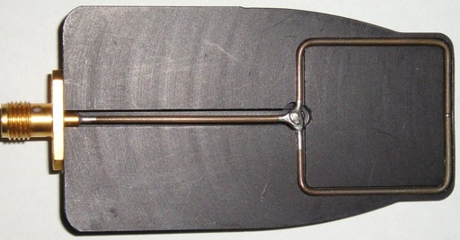
Figure 1. A Shielded Loop Built From Semi-rigid Coax
Abstract: It is generally
acknowledged by EMC engineers that far field emissions cannot be
reliably predicted by a near field measurement of electric or magnetic
fields. However, there is an exception to this rule. Structures that
are physically too small themselves to radiate efficiently at a given
frequency may couple energy into larger structures, such as cables,
that may then radiate significant emissions. Magnetic fields capable of
doing this are easily measured by loop probes.
Discussion: Figure 1
shows a shielded magnetic loop probe
constructed using semi-rigid coax cable (note the small gap in the
shield at the midpoint of the right side of the loop). Figure 2 shows
an example of an unshielded magnetic loop probe constructed from stiff
wire and heat shrink tubing on the end of a BNC barrel adapter. Either
of these loops can be used to measure possible effects of a local
magnetic field that can couple onto cables and thus causes far field
emissions from the cable. I prefer square loops to round ones as most
cables are relatively straight, not curved in an arc that matches the
curvature of a specific round loop probe.
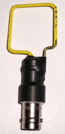
Figure 2. A Simple Wire Loop
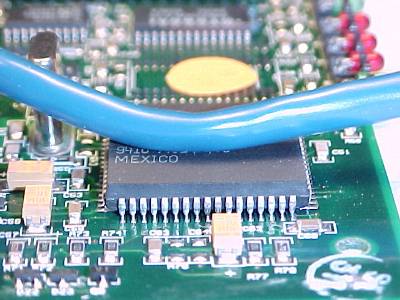
The situation of concers is illustrated in Figure 3. In this case, a physically small magnetic field couples from an IC to a system cable. The magnetic field emitted from the IC induces a series voltage in the cable which then causes a current to flow resulting in emissions. If we assume the driving point impedance of the cable at the IC is 100 Ohms (the driving point impedance of a dipole at resonance is about 70 Ohms, but I will use 100 Ohms as a round number) then only about 1 millivolt of induced signal will generate current on the cable of 10 microamps, enough to be a potential class B (consumer equipment) emissions problem. See my March 2006 Technical Tidbit, Predicting Cable Emissions from Common Mode Current for more information on common mode currents and emissions.
A situation like this can be predicted by using a magnetic loop probe. First construct a square probe with the length of a side approximately equal to the distance across the IC. A plain wire loop like that shown in Figure 2 will do. If the probe is positioned over the IC, perpendicular to the plane of the IC package and with the side of the loop opposite its cable against the IC package, the resulting loop output signal can be used to predict emissions if an appropriate length cable scan intercept the field of the IC. The loop should be rotated and moved over the package to pick up the maximum signal possible at each frequency of interest. If a magnetic field loop probe is positioned over the loop and picks up two millivolts into the 50 Ohm input of a spectrum analyzer, then a cable might pick up a similar voltage if positioned over the IC. Two millivolts driving 100 Ohms will result in 20 micropamps of current, enough to be even a Class A (industrial equipment) emission problem.
Similarly, a wire loop can measure the possible induction into cables from other sources, such as a switching power supply. I generally find a one inch square loop to be a good size. The side of the loop opposite its feed cable is placed where a system cable could be located to estimate the signal induced into such a cable. Larger loops could be used, but when the circumference of the loop is 1/2 wavelength at the frequency of interest, the loop goes into resonance itself and becomes less useful.
The surface of a circuit board can be scanned using a square magnetic loop probe and areas of the board than can induce a millivolt at any frequency into the loop can be dangerous if a cable can drop onto the board at that point and then exit the enclosure.
Cable radiation due to interception of local fields is easy to demonstrate. Just put a current probe on a cable and place the cable near the current probe on top of an active IC of good size and watch the common mode current on the cable increase as the cable is brought near the IC.
Figure 2. A Simple Wire Loop
The situation of concers is illustrated in Figure 3. In this case, a physically small magnetic field couples from an IC to a system cable. The magnetic field emitted from the IC induces a series voltage in the cable which then causes a current to flow resulting in emissions. If we assume the driving point impedance of the cable at the IC is 100 Ohms (the driving point impedance of a dipole at resonance is about 70 Ohms, but I will use 100 Ohms as a round number) then only about 1 millivolt of induced signal will generate current on the cable of 10 microamps, enough to be a potential class B (consumer equipment) emissions problem. See my March 2006 Technical Tidbit, Predicting Cable Emissions from Common Mode Current for more information on common mode currents and emissions.
Figure 3. System Cable Near an IC
A situation like this can be predicted by using a magnetic loop probe. First construct a square probe with the length of a side approximately equal to the distance across the IC. A plain wire loop like that shown in Figure 2 will do. If the probe is positioned over the IC, perpendicular to the plane of the IC package and with the side of the loop opposite its cable against the IC package, the resulting loop output signal can be used to predict emissions if an appropriate length cable scan intercept the field of the IC. The loop should be rotated and moved over the package to pick up the maximum signal possible at each frequency of interest. If a magnetic field loop probe is positioned over the loop and picks up two millivolts into the 50 Ohm input of a spectrum analyzer, then a cable might pick up a similar voltage if positioned over the IC. Two millivolts driving 100 Ohms will result in 20 micropamps of current, enough to be even a Class A (industrial equipment) emission problem.
Similarly, a wire loop can measure the possible induction into cables from other sources, such as a switching power supply. I generally find a one inch square loop to be a good size. The side of the loop opposite its feed cable is placed where a system cable could be located to estimate the signal induced into such a cable. Larger loops could be used, but when the circumference of the loop is 1/2 wavelength at the frequency of interest, the loop goes into resonance itself and becomes less useful.
The surface of a circuit board can be scanned using a square magnetic loop probe and areas of the board than can induce a millivolt at any frequency into the loop can be dangerous if a cable can drop onto the board at that point and then exit the enclosure.
Cable radiation due to interception of local fields is easy to demonstrate. Just put a current probe on a cable and place the cable near the current probe on top of an active IC of good size and watch the common mode current on the cable increase as the cable is brought near the IC.
Summary:
Using a (square) magnetic loop probe to find areas of risk for cables
in a system is a useful EMC troubleshooting method. Areas of the system
that can induce one or two millivolts at a frequency in the loop are at
risk and cables should be kept away from those areas if they are long enough to radiate
the frequeny picked up by the loop and then exit the system enclosure.
Additional articles on this website related to this topic are:
- March 2006, Predicting Cable Emissions from Common Mode Current
- Radiation from Common Mode Currents - Beyond 1 GHz (~1.2 MB) short paper by Mat Aschenberg and Charles Grasso
- February 2005, Crossing Ground Plane Breaks - Part 5, Common Mode Currents and Emissions
- April 2003, Measurement and Interpretation of High Frequency Chip Noise
- March 2002, Cable Effects Part 3: Capacitive Pickup by Cables in a System
- February 2002, Cable Effects Part 2: Inductive Pickup by Cables in a System
- December 2000, An Easy to Build Shielded Magnetic Loop Probe
-
Signal and Noise Measurement Techniques Using
Magnetic Field Probes (~600K)
(1999 IEEE EMC Symposium paper) -
Current Probes, More Useful
Than You Think (~170K)
(1998 IEEE EMC Symposium paper)
Click here for a description of my latest seminar titled (now also available online as a WebEx seminar):
EMC
Lab Techniques for Designers
(How to find EMC problems and have some confidence your system will pass EMC testing while it is still in your lab).
(How to find EMC problems and have some confidence your system will pass EMC testing while it is still in your lab).
 |
My new website for engineers and technicians, CircuitAdvisor.com, is coming! The site will contain technews and analysis programs, cartoons, multimedia tutorials and more.The site will be open soon. |
Home