Cable Effects Part 3: Capacitive Pickup by Cables in a System
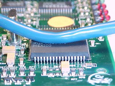
Figure 1. Cable Subjected to Fields from an IC

Address: P. O. Box 1457, Los Gatos,
CA 95031
TEL:
800-323-3956/408-356-4186
FAX:
408-358-3799
Mobile: 408-858-4528
URL:
www.dsmith.org
Email: doug@dsmith.org
Figure 1. Cable Subjected to Fields from an IC
This Technical Tidbit is the third in a series of articles on cable effects.
Internal cables in systems can pickup fields radiated from devices and the board itself. Resulting currents induced in the cables can conduct noise into other parts of the system or cause emission problems if those cables are not contained within a shielded enclosure. The situation pictured in Figure 1 is not all that uncommon, a system cable is allowed to come close to an integrated circuit. The amount of noise current induced in the cable can be significant and more than one might imagine.
Figure 2 shows the amount of current capacitively coupled to a 4 m long UTP Category 5 cable (similar to the one shown in Figure 1) from an HC240 gate output. Upper and lower traces in Figure 2 represent the outputs of two matched Fischer F-33-1 current probes positioned on each side of the location were the signal was coupled into the wire, as shown in Figure 3. A 3 cm wide copper foil tape capacitively coupled a 5 volt square wave at approximately 46 MHz with a risetime of about 2 ns onto the category 5 cable. The resulting signal on the cable excited a cable resonance.
Figure 2. Common Mode Current Induced on a 4 Meter UTP Cable
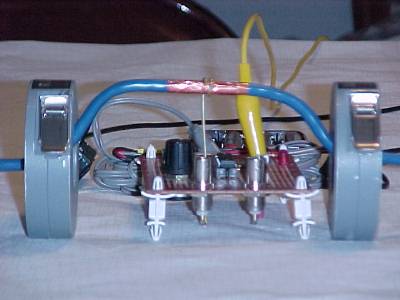
Figure 3. Current Probe and Oscillator Test Setup
Note that the waveforms in Figure 2 are out of phase. This confirms capacitive coupling (as opposed to inductive coupling). Capacitive coupling manifests itself as a current flowing away from the coupling point in the receiving conductor, and hence the opposite current directions. If the coupling were primarily inductive, the phases would have been the same. See the February, 2002 Technical Tidbit for a discussion of inductive coupling.
The amplitude of the current in Figure 2 is about 10 mA peak. If we estimate a value of 5 mA rms for the current component at 46 MHz, then the current magnitude would likely radiate about 1000 times the level allowed by international emissions requirements for Class B equipment (consumer) at this frequency, a 60 dB failure!. Common mode currents on the order of 5 to 15 microamps are capable of becoming an emissions problem.
Although the capacitive coupling from an integrated circuit to the cable would likely be weaker than the 3 cm wrap of copper tape used here, the current in this example is about 1000 times more than needed to fail emissions requirements. A coupling capacitance of only one tenth of the copper tape would likely still couple 100 times the current needed for a failure!
Executive Summary: Control system cable placement in your next design!
Note: Currents in the range of tens of microamps are not readily observable
on a scope, however a spectrum analyzer can measure these kind of amplitudes
easily. The phase between two current probes can also be displayed on a
spectrum analyzer to confirm the inductive or capacitive mode. A technique
for doing this is described in my 1998 IEEE EMC Symposium paper "Current
Probes, More Useful Than You Think."