
Figure 1. Test Setup For Measuring Pulse Induced by Current Probe into Multi-turn Coil
Abstract: Current probes can
be used to inductively couple voltage pulses into cables for troubleshooting without needing a direct
connection to the circuit. This concept is extended to using multiple
turns through the current probe to increase the injected voltage.
Discussion: In the December 2007 Technical Tidbit,
current probes were shown to be a convenient method of injecting
series voltage pulses in circuits for troubleshooting.
However, the amount of injected voltage may not be enough, 50 to 100
Volts was demonstrated in the December article, to cause the desired response. Figure 1 shows the test
setup used to measure the injected voltage when a wire was wrapped
through the current probe for multiple turns. This will increase the
injected voltage at the expense of additional series source impedance in the
circuit to be stressed. Figure 2 shows a close-up of the wire wrapped on
the current probe with the wire passing through the current probe four times. The induced voltage was measured using an Agilent
1163a 10:1 resistor divider probe with a 500 Ohm input impedance.
Figure 4 shows the induced voltage peaking at about 28 Volts for a 60 Volt drive from the TG-EFT. This means that with a drive of 400 Volts from the TG-EFT, the maximum I have used with the F-33-1 current probe, injected voltages of around 200 Volts are possible. Additional turns could be added on the current probe to yield higher induced voltages. At some point, parasitic capacitance in the coil, its inductance, or physical size compared to the frequency components in the pulse will become a problem. I recommend checking the injected pulse with an oscilloscope to make sure you are getting the pulse that is desired.
Note in Figure 4 the fast rising edge and long tail which is the shape of the output pulse of the TG-EFT. The dip below zero Volts is an artifact of the current probe being AC coupled. The area under the curve must be the same above zero Volts as it is below zero Volts averaged over time.
Figure 4. Measured Pulse using Four Turns of Wire Around Current Probe
(Vertical scale = 10 Volts/div, Horizontal scale = 50 ns/div)
Figure 5 shows the same waveform expanded out from 50 ns/div to 2 ns/div to show a rise of about four nanoseconds to the peak from the baseline. The peak of ~28 Volts is more clearly seen in this view.
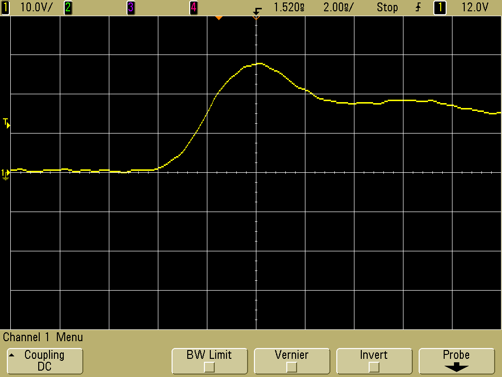
Figure 5. Measured Pulse Using Four Turns of Wire Around Current Probe - Expanded
(Vertical scale = 10 Volts/div, Horizontal scale = 2 ns/div)
Figure 6 shows a measurement using just one turn through the F-33-1 current probe, in this case the ground lead of the scope probe. This is similar to one of the measurements described in the December 2007 Technical Tidbit. A close-up of the current probe and scope probe appears in Figure 7.
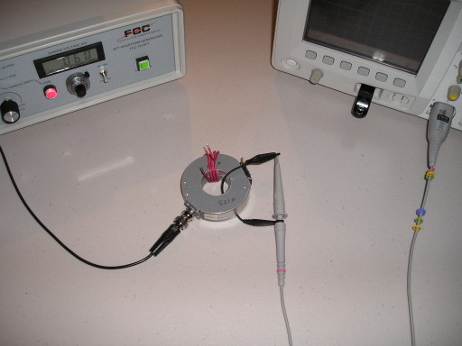
Figure 6. Test Setup For Measuring Pulse Induced by Current Probe into a Single Turn
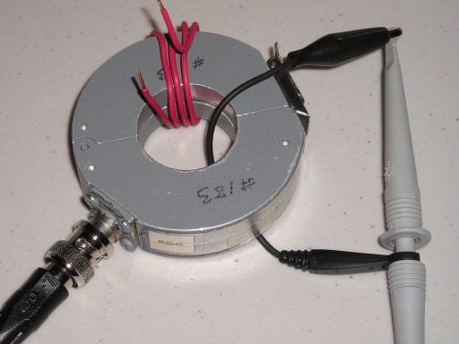
Figure 7. Close-up of Current and 1163 Resistive Divider Scope Probe
Figure 8 shows the induced voltage into the 1163A probe, for a 60 Volt drive from the TG-EFT, peaking at about 7.7 Volts. Figure 9 expands the time scale from 50 ns/div to 2 ns/div where the peak at 7.7 volts can be seen more clearly. The rise from the baseline to peak is about three nanoseconds. This is faster than the rise of four nanoseconds of the four turn case because of lowered series inductance and less capacitance to the current probe body resulting in less filtering for the single turn case. These added effects of the four turn coil are responsible for both the longer risetime and flatter peak in Figure5 versus the peak in Figure 9 for the single turn case.
The ratio of the induced voltage between four turns and one turn is 28/7.7 = ~3.6 a little lower than the turns ratio of 4:1 because the input impedance of the probe represents more of a load on the four turn coil as well as the filtering effects described in the last paragraph.
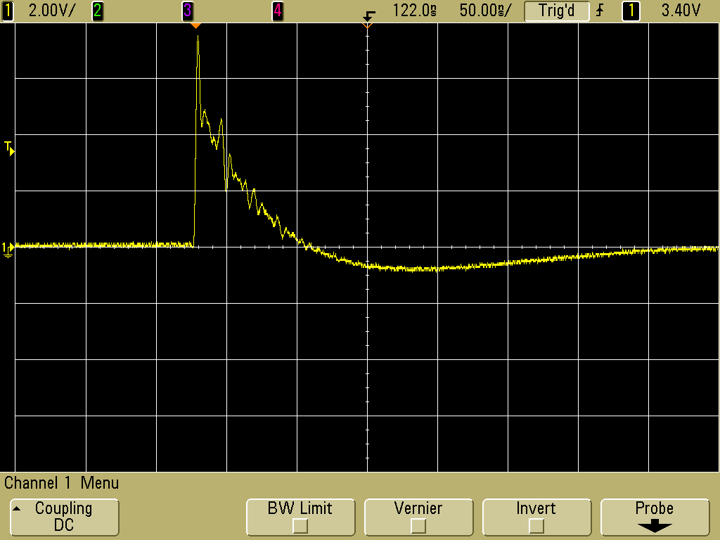
Figure 8. Measured Pulse using One Turn Around Current Probe
(Vertical scale = 2 Volts/div, Horizontal scale = 50 ns/div)
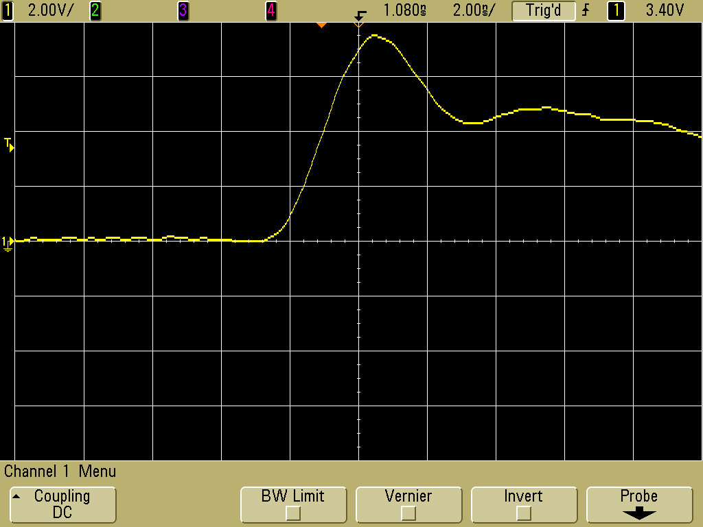
Figure 9. Measured Pulse Using One Turn Around Current Probe - Expanded
(Vertical scale = 2 Volts/div, Horizontal scale = 2 ns/div)
The F-33-1 current probe contains just a magnetic core surrounded by a coil and handles the pulses from the TG-EFT well. Some current probes, such as the Fischer F-65 and F-33-2 probes, contain resistive networks to modify the current probe frequency and amplitude response. Probes such as these with internal resistive networks should not be used to inject pulses as the required high voltage pulses applied to the current probe may damage the resistive network.
Figure 2. Close-up of Wire Wrapped on Current Probe
A Fischer Custom Communications TG-EFT high voltage pulse generator was used to drive an F-33-1 current probe for this article. As shown in Figure 3, its output was set to just ~60 Volts to keep the scope from being overdriven.Figure 3. Setting the TG-EFT at 60 Volts for the Measurements
Figure 4 shows the induced voltage peaking at about 28 Volts for a 60 Volt drive from the TG-EFT. This means that with a drive of 400 Volts from the TG-EFT, the maximum I have used with the F-33-1 current probe, injected voltages of around 200 Volts are possible. Additional turns could be added on the current probe to yield higher induced voltages. At some point, parasitic capacitance in the coil, its inductance, or physical size compared to the frequency components in the pulse will become a problem. I recommend checking the injected pulse with an oscilloscope to make sure you are getting the pulse that is desired.
Note in Figure 4 the fast rising edge and long tail which is the shape of the output pulse of the TG-EFT. The dip below zero Volts is an artifact of the current probe being AC coupled. The area under the curve must be the same above zero Volts as it is below zero Volts averaged over time.
Figure 4. Measured Pulse using Four Turns of Wire Around Current Probe
(Vertical scale = 10 Volts/div, Horizontal scale = 50 ns/div)
Figure 5 shows the same waveform expanded out from 50 ns/div to 2 ns/div to show a rise of about four nanoseconds to the peak from the baseline. The peak of ~28 Volts is more clearly seen in this view.
Figure 5. Measured Pulse Using Four Turns of Wire Around Current Probe - Expanded
(Vertical scale = 10 Volts/div, Horizontal scale = 2 ns/div)
Figure 6 shows a measurement using just one turn through the F-33-1 current probe, in this case the ground lead of the scope probe. This is similar to one of the measurements described in the December 2007 Technical Tidbit. A close-up of the current probe and scope probe appears in Figure 7.
Figure 6. Test Setup For Measuring Pulse Induced by Current Probe into a Single Turn
Figure 7. Close-up of Current and 1163 Resistive Divider Scope Probe
Figure 8 shows the induced voltage into the 1163A probe, for a 60 Volt drive from the TG-EFT, peaking at about 7.7 Volts. Figure 9 expands the time scale from 50 ns/div to 2 ns/div where the peak at 7.7 volts can be seen more clearly. The rise from the baseline to peak is about three nanoseconds. This is faster than the rise of four nanoseconds of the four turn case because of lowered series inductance and less capacitance to the current probe body resulting in less filtering for the single turn case. These added effects of the four turn coil are responsible for both the longer risetime and flatter peak in Figure5 versus the peak in Figure 9 for the single turn case.
The ratio of the induced voltage between four turns and one turn is 28/7.7 = ~3.6 a little lower than the turns ratio of 4:1 because the input impedance of the probe represents more of a load on the four turn coil as well as the filtering effects described in the last paragraph.
Figure 8. Measured Pulse using One Turn Around Current Probe
(Vertical scale = 2 Volts/div, Horizontal scale = 50 ns/div)
Figure 9. Measured Pulse Using One Turn Around Current Probe - Expanded
(Vertical scale = 2 Volts/div, Horizontal scale = 2 ns/div)
The F-33-1 current probe contains just a magnetic core surrounded by a coil and handles the pulses from the TG-EFT well. Some current probes, such as the Fischer F-65 and F-33-2 probes, contain resistive networks to modify the current probe frequency and amplitude response. Probes such as these with internal resistive networks should not be used to inject pulses as the required high voltage pulses applied to the current probe may damage the resistive network.
Summary:
Current probes can be used to induce series voltage impulses in cables. The
induced voltage can be increased at the expense of increased
risetime by increasing the number of turns of the cable through the
current probe. Four turns were shown to work well for this purpose.
Current probes with resistive networks in them such as the F-65 and
F-33-2 should not be used in this way to avoid damaging the networks in the probes.
Additional articles on this website related to this topic are:
- Current Probes, More Useful
Than You Think (~170K)
(1998 IEEE EMC Symposium paper) - June 1999: The Dual Current Probe Problem
- September 1999: Measuring Voltages Using Current Probes
- August 2001, Differential Measurement of Cable EMI Currents
- October 2007, Using Noise Injection for Troubleshooting Circuits
- December 2007, Using Current Probes to Inject Pulses for Troubleshooting
(Current Probes, More Useful Than You Think - Part 2)
- The scope used in this Technical Tidbit is an Agilent DSO5054A, a great little scope that is easy to use and boots in 9 seconds flat!
- The Agilent 1163a probe is a 10:1 resistive divider probe with over 1 GHz bandwidth.
- The Fischer Custom Communications F-33-1 current probe used in this article is popular with EMC engineers for measuring common mode EMI currents and is widely available in many test labs.
- Fischer Custom Communications TG-EFT high voltage pulse generator
Click here for a description of my latest seminar titled (now also available online as a WebEx seminar):
EMC
Lab Techniques for Designers
(How to find EMC problems and have some confidence your system will pass EMC testing while it is still in your lab).
(How to find EMC problems and have some confidence your system will pass EMC testing while it is still in your lab).
 |
Check
out my podcast containing mp3 format short tutorials, tech news and
more! Just click on the
microphone to see the listing
of free
audio programs. Content is added every week on technical
topics so check back frequently. |
Home