
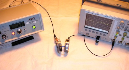
Figure 1. Experimental Setup with Current Probes and Current Loop
Abstract:
A technique for
using current probes to inductively couple pulses into circuits for
troubleshooting designs is described. Significant voltages can be
coupled in series with wires and cables. Coupled pulses of
several tens
of Volts are easy to achieve. This technique can be especially useful
in troubleshooting ESD problems as well as other noise ralated problems
in designs.
Discussion:
This Technical Tidbit could be considered an extension of my
1998 IEEE EMC Symposium paper "Current Probes, More Useful
Than You Think."
In that paper, current measurements were made in the frequency and time
domain. In this Technical Tidbit, I am turning the current probe around
and using it to inductively couple pulses into wires and cables. Bulk
injection probes are usually used for signal injection, but they are
large,
heavy, and designed to handle tens of Watts or more of continuous high
frequency power. In this case, I use a current probe for the same
purpose but for pulses instead of continuous sinusoidal signals.
Although the injected pulses have a high peak value, the
average power is very low as the pulses used last tens of nanoseconds and
are
tens of milliseconds or further apart, allowing the use of current
probes without worrying about heating of the probe.
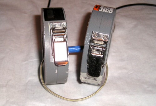
Figure 1 shows the experimental setup using a Fischer Custom Communications (FCC) TG-EFT pulse generator, an Agilent DSO5054A oscilloscope, an FCC F-65 current probe, and an FCC F-33-1 current probe. For the purposes of the experiments described in this Technical Tidbit, the pulses were coupled into the circuit from the pulse generator by an F-33-1 current probe and the resulting current measured with an FCC F-65 current probe. Figure 2 shows a view of the TG-EFT pulse generator.
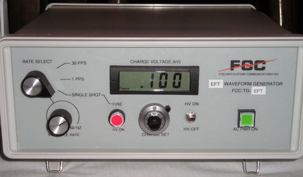
Figure 2. Fischer Custom Communications TG-EFT Pulse Generator
The TG-EFT pulse generator was set to 100 Volts open circuit for this test. The F-33-1 current probe is composed of several turns of wire around a magnetic core and essentially forms a transformer to the wire passing through it. This makes it ideal for injecting pulses. The F-65 current probe has internal networks to modify its sensitivity and frequency response. A probe such as this should not be used for injecting pulses except at low levels as the network may be damaged at higher pulse levels. As a current probe the F-65 can handle 100 Ampere pulses resulting in a 100 Volt probe output. I have fed 100 Volt pulses from the TG-EFT into my F-65 with no ill effect as expected. In fact, Figure 1 shows the TG-EFT driving an F-65 with 100 Volt pulses.
For a probe such as the F-33-1, insulation and saturation are the main considerations when feeding high voltage pulses into its BNC connector. I fed my F-33-1 as much as 400 Volt pulses from the TG-EFG with no saturation or breakdown resulting. The insulation on the windings in the probe is good so it should go even higher, although I did not test above pulse amplitudes of 400 Volts.
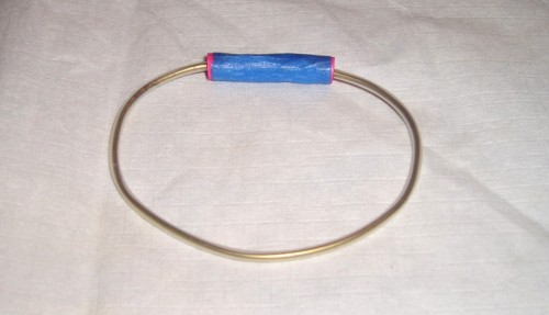
Figure 3 shows the wire loop used for one of the experiments to follow. It is composed of AWG 16 stiff brass wire joined by a crimp connector at the ends to form a loop. The wire is covered with heat shrink tubing and forms a loop with about a seven inch (~17 cm) circumference.
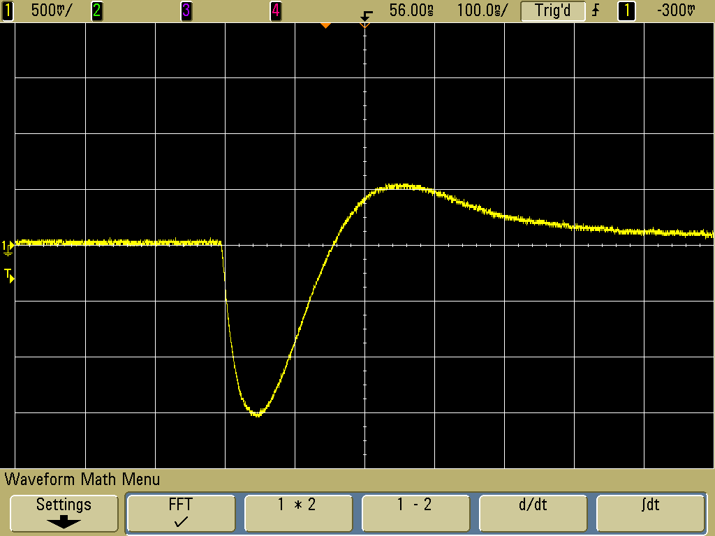
In order to measure the value of the coupled open circuit voltage into circuits, an F-33-1 current probe was driven from the TG-EFT and placed around the ground lead of an Agilent 1163a resistive divider probe. The 1163a probe has a 500 Ohm resistive input impedance (with around 1 pF of capacitance), a 10:1 probe attenuation factor, and a bandwidth in excess of 1 GHz. Figure 4 shows the test configuration. The probe's 500 Ohm input impedance reflects back through the current probe towards the generator as a much higher impedance in the many thousands of Ohms, so the test measures the open circuit injected voltage into a test circuit.
Figure 5 shows shows the measured result from the circuit of Figure 4 with the TG-EFT generator set at 100 Volts. The peak voltage injected into the probe circuit is almost 10 Volts. I have tried the F-33-1 up to 400 Volts from the TG-EFT with no ill effect, so series pulsed voltages around 40 Volts or more are possible into wires and cable using an F-33-1.
If the winding on the F-33-1 were a single turn instead of several turns, the peak voltage would be higher, but the pulse width would be less because of reduced frequency response of the probe at the low end if the same magnetic core is used. The turns ratio of the F-33-1 gives the injected pulses a low impedance, ideal for launching pulses on a ground grid such as used in some facility grounding systems. A current probe with only one turn on its core might be better for injecting pulses on long cables, a higher impedance load.
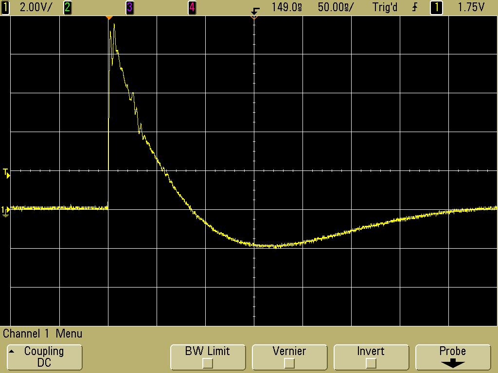
Figure 5. Injected Open Circuit Pulse
(vertical scale = 2 V/div, horizontal scale = 50 ns/div)
The 50 ns/div horizontal scale of Figure 5 is expanded to 10 ns/div in Figure 6 to show greater detail on the waveform. The small wiggles on the waveform are diminishing reflections between the current probe and the TG-EFT. Since the current probe is AC coupled, the area above zero Volts and below it must be the same. This is why the trace goes negative in Figure 5.
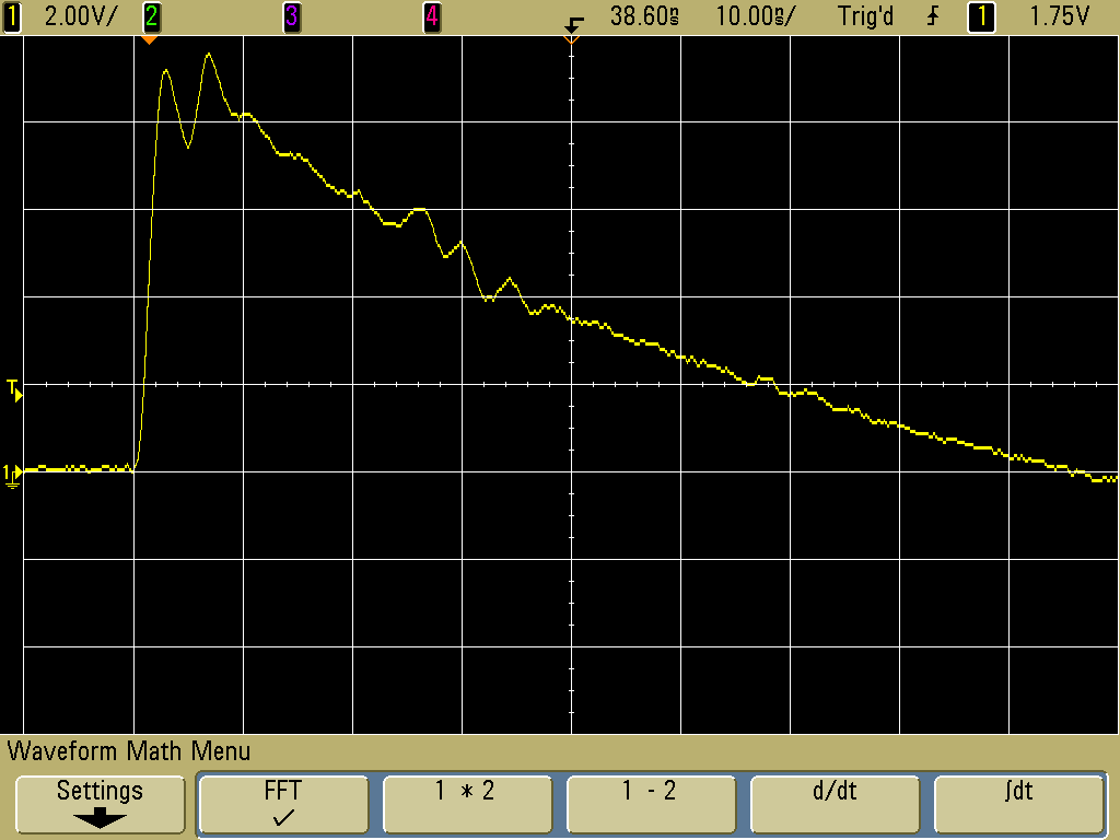
Figure 6. Injected Open Circuit Pulse
(vertical scale = 2 V/div, horizontal scale = 10 ns/div)
Figure 7 shows the F-33-1 on the left injecting voltage into the wire loop of Figure 3 with the F-65 on the right connected to the oscilloscope. The output of the F-65 is shown in Figure 8.
Notice that the risetime of the current in Figure 8 is on the order of 20 ns whereas the injected voltage from Figure 6 is about 2 ns. The reason is the inductance of the wire loop. Remember that:
So we must integrate E(t)/L over time to get i(t) and therefore the current rises more slowly than the driving voltage. The larger the loop inductance of the wire loop, the lower the value of peak current given the time limited driving pulse from the TG-EFT.
Figure 1 shows the experimental setup using a Fischer Custom Communications (FCC) TG-EFT pulse generator, an Agilent DSO5054A oscilloscope, an FCC F-65 current probe, and an FCC F-33-1 current probe. For the purposes of the experiments described in this Technical Tidbit, the pulses were coupled into the circuit from the pulse generator by an F-33-1 current probe and the resulting current measured with an FCC F-65 current probe. Figure 2 shows a view of the TG-EFT pulse generator.
Figure 2. Fischer Custom Communications TG-EFT Pulse Generator
The TG-EFT pulse generator was set to 100 Volts open circuit for this test. The F-33-1 current probe is composed of several turns of wire around a magnetic core and essentially forms a transformer to the wire passing through it. This makes it ideal for injecting pulses. The F-65 current probe has internal networks to modify its sensitivity and frequency response. A probe such as this should not be used for injecting pulses except at low levels as the network may be damaged at higher pulse levels. As a current probe the F-65 can handle 100 Ampere pulses resulting in a 100 Volt probe output. I have fed 100 Volt pulses from the TG-EFT into my F-65 with no ill effect as expected. In fact, Figure 1 shows the TG-EFT driving an F-65 with 100 Volt pulses.
For a probe such as the F-33-1, insulation and saturation are the main considerations when feeding high voltage pulses into its BNC connector. I fed my F-33-1 as much as 400 Volt pulses from the TG-EFG with no saturation or breakdown resulting. The insulation on the windings in the probe is good so it should go even higher, although I did not test above pulse amplitudes of 400 Volts.
Figure 3 shows the wire loop used for one of the experiments to follow. It is composed of AWG 16 stiff brass wire joined by a crimp connector at the ends to form a loop. The wire is covered with heat shrink tubing and forms a loop with about a seven inch (~17 cm) circumference.
Figure 3. Wire Loop Used for Pulse Injection Measurement
In order to measure the value of the coupled open circuit voltage into circuits, an F-33-1 current probe was driven from the TG-EFT and placed around the ground lead of an Agilent 1163a resistive divider probe. The 1163a probe has a 500 Ohm resistive input impedance (with around 1 pF of capacitance), a 10:1 probe attenuation factor, and a bandwidth in excess of 1 GHz. Figure 4 shows the test configuration. The probe's 500 Ohm input impedance reflects back through the current probe towards the generator as a much higher impedance in the many thousands of Ohms, so the test measures the open circuit injected voltage into a test circuit.
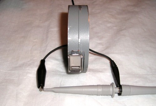
Figure 5 shows shows the measured result from the circuit of Figure 4 with the TG-EFT generator set at 100 Volts. The peak voltage injected into the probe circuit is almost 10 Volts. I have tried the F-33-1 up to 400 Volts from the TG-EFT with no ill effect, so series pulsed voltages around 40 Volts or more are possible into wires and cable using an F-33-1.
If the winding on the F-33-1 were a single turn instead of several turns, the peak voltage would be higher, but the pulse width would be less because of reduced frequency response of the probe at the low end if the same magnetic core is used. The turns ratio of the F-33-1 gives the injected pulses a low impedance, ideal for launching pulses on a ground grid such as used in some facility grounding systems. A current probe with only one turn on its core might be better for injecting pulses on long cables, a higher impedance load.
Figure 5. Injected Open Circuit Pulse
(vertical scale = 2 V/div, horizontal scale = 50 ns/div)
The 50 ns/div horizontal scale of Figure 5 is expanded to 10 ns/div in Figure 6 to show greater detail on the waveform. The small wiggles on the waveform are diminishing reflections between the current probe and the TG-EFT. Since the current probe is AC coupled, the area above zero Volts and below it must be the same. This is why the trace goes negative in Figure 5.
Figure 6. Injected Open Circuit Pulse
(vertical scale = 2 V/div, horizontal scale = 10 ns/div)
Figure 7 shows the F-33-1 on the left injecting voltage into the wire loop of Figure 3 with the F-65 on the right connected to the oscilloscope. The output of the F-65 is shown in Figure 8.
Figure 7. F-33-1 as the Injection Probe and F-65 as the
Sensing Probe
Figure 8. Measured Current in Wire Loop by F-65 Current Probe
(vertical scale = 1/2 Amp/div, horizontal scale = 100 ns/div)
(vertical scale = 1/2 Amp/div, horizontal scale = 100 ns/div)
Notice that the risetime of the current in Figure 8 is on the order of 20 ns whereas the injected voltage from Figure 6 is about 2 ns. The reason is the inductance of the wire loop. Remember that:
E(t) =
L·di(t)/dt
So we must integrate E(t)/L over time to get i(t) and therefore the current rises more slowly than the driving voltage. The larger the loop inductance of the wire loop, the lower the value of peak current given the time limited driving pulse from the TG-EFT.
Summary: A
method of using a pulse generator and a current probe to inject
pulses of several tens of Volts in series with wires and cables is described. This
method can be used to find ESD and other noise problems in equipment.
A current probe consisting of only a winding and a magnetic core (and no internal networks) is best suited for pulse injection. The F-33-1 is widely available in the field and its turns ratio helps match a low impedance loop to the generator and feed coax making it a good choice. Pulses can also be injected from a pulse generator using standard bulk injection probes used for RFI immunity tests.
A current probe consisting of only a winding and a magnetic core (and no internal networks) is best suited for pulse injection. The F-33-1 is widely available in the field and its turns ratio helps match a low impedance loop to the generator and feed coax making it a good choice. Pulses can also be injected from a pulse generator using standard bulk injection probes used for RFI immunity tests.
Additional articles on this website related to this topic are:
- Current Probes, More Useful
Than You Think (~170K)
(1998 IEEE EMC Symposium paper) - June 1999: The Dual Current Probe Problem
- September 1999: Measuring Voltages Using Current Probes
- August 2001, Differential Measurement of Cable EMI Currents
- October 2007, Using Noise Injection for Troubleshooting Circuits
- The scope used in this Technical Tidbit is an Agilent DSO5054A, a great little scope that is easy to use and boots in 9 seconds flat!
- The Agilent 1163a probe is a 10:1 resistive divider probe with over 1 GHz bandwidth.
- The Fischer Custom Communications F-33-1 current probe is popular with EMC engineers for measuring common mode EMI currents and is widely available in many test labs.
- Fischer Custom Communications F-65 current probe has a one Volt per Amp output and very wide bandwidth making it excellent for measuring ESD, EFT, and other pulsed currents.
Click here for a description of my latest seminar titled:
EMC
Lab Techniques for Designers
(How to find EMC problems and have some confidence your system will pass EMC testing while it is still in your lab).
(How to find EMC problems and have some confidence your system will pass EMC testing while it is still in your lab).
 |
Check
out my podcast containing mp3 format short tutorials, tech news and
more! Just click on the
microphone to see the listing
of free
audio programs. Content is added every week on technical
topics so check back frequently. |
Home