Crossing Ground Plane Breaks - Part 3
Immunity to Radiated EMI
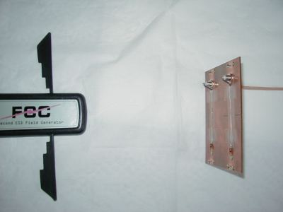
Figure 1. Radiated EMI Test Setup

Address: P. O. Box 1457, Los Gatos,CA 95031
TEL: 800-323-3956/408-356-4186
FAX: 408-358-3799
Mobile: 408-858-4528
URL: www.dsmith.org
Email: doug@dsmith.org
Figure 1. Radiated EMI Test Setup
Abstract: In this article, the last in a three part series on the effects of paths crossing ground plane breaks, theeffects of immunity to impulsive electromagnetic fields are investigated. As one mightexpect, the data presented shows a significant loss of immunity to EMI forsignal paths that cross a ground plane break as compared to paths that remainover a solid ground plane.
Discussion: Figure 1 shows a circuit board placed 20 cm from a source of EMI (~450K pdf file) that simulates fast pulses caused by low voltage ESD, a significantproblem in custsomer environments. The board itself is shown in Figure 2.The upper path crosses a slot in the ground plane about 5 cm in length. Thepaths are 24 gauge wire taped down to a circuit board to form approximate50 Ohm transmission lines terminated by the resistors on the right. The fourwire loops soldered to the ground plane facilitate connections to the groundplane for other experiments and are not used in this test.
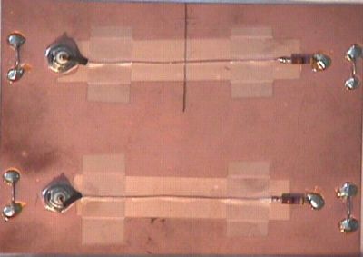
Figure 3. Signal from Path Over Solid Ground
(Vertical scale = 100 mV/div, Horizontal scale = 5 ns/div)
Compare Figure 3 to the scope screen shown in Figure 4. Figure 4 was taken using the paththat crosses the ground break. The amplitude of the signal is over 3 Volts peak (the scale has been changed from 100 mV/div to 1 V/div) in Figure 4!
Figure 4. Signal from Path Over Broken Ground
(Vertical scale = 1 V/div, Horizontal scale = 5 ns/div)
This result could be expected from the analysis of signal currents on the board in the January 2003 Technical Tidbit, "Crossing Ground Plane Breaks - Part 2, Tracing Current Paths." The article showed a significant loop is formed composed of the signalpath and the return path in the ground plane that is forced to go aroundthe end of the ground plane break. As can be seen from the data above, such a loop makes a great antenna.
For related information pertaining to this article on this website see:
The waveforms in this article were taken with an AgilentInfinium 54845a oscilloscope.