High Frequency MeasurementsWeb Page
Douglas C. Smith Address: P. O. Box 1457, Los Gatos,CA 95031
TEL: 800-323-3956/408-356-4186
FAX: 408-358-3799
Mobile: 408-858-4528
URL: www.dsmith.org
Email: doug@dsmith.org
Technical Tidbit - November 2002Measuring Noise Voltage Across Seams in Enclosures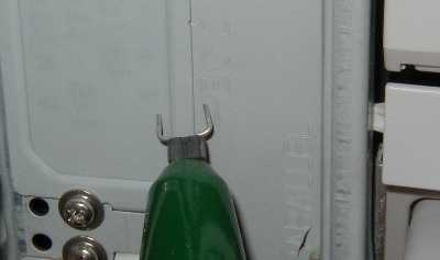
Figure 1. Voltage Measurement Across Seam Using Differential Probe
Seams and slots in equipment enclosures can result in emissions leakagethat affect radiated emissions compliance. Often EMC personnel will use magneticloops to find such leakage. This Technical Tidbit covers an alternate wayto investigate radiation from seams and slots using a voltage measurementthat can be roughly correlated to the emissions.
Figure 1 shows a high bandwidth (1.8 GHz) differential probe (~400K file) being usedto measure the voltage across a seam in a chassis. With proper interpretation,this measurement can give an estimate of the emissions potential of thisseam.If the dimensions of the seam and the surrounding metal are a substantialfraction of a wavelength at a frequency of interest, then one couldconsider the metal as an antenna to be driven by the voltage across the seam.
A dipole that is tuned to 1/2 wavelength at the frequency of interest,has a low driving point input impedance (~70 Ohms). Under this condition,it takes only about 15 microamps of current to causes a a potential ClassA (industrial) emissions compliance problem. The voltage input to the dipolenecessary to drive a current of 15 microamps into 70 Ohms is only about 1mV.
The metal may have a much broader spectrum over which it can radiate than a dipole. However, if we use the same numbersas for a dipole (we are only looking for an estimate), then a voltage acrossthe seam on the order of a few millivolts (due to currents or fields insideof the enclosure) might be a problem for emissions. It is currentthat results in radiation in the far field where emissions are measured. The questionis whether a voltage across the seam will result in a current that will, in turn, flow onthe outside surface of the metal enclosure that is sufficient to result in emission problems.
There are a few points to consider.
- Is the measured voltage due to a source internal to the equipment?Turn off the equipment to find out. I call this a null experiment.
- Is the measured voltage due to voltage across the seam, as opposed to probe commonmode response? Short the probe tips together and then to each side of theseam, one side at a time. This is another null experiment. The result shouldbe much lower than the measured voltage across the slit. The result of thisnull experiment (shorting the probe tips) will also indicate if a magneticfield in the area is inducing a voltage into the probe tip loop in accordancewith the descriptions of Faraday's law. In either case, if the shorted proberesponse is similar to the measured voltage across the slot (or seam), itmay not be possible to make this voltage measurement.
- If the measured voltage is really across the seam,the final question to answer is: Does that voltage result in current flow?Without current flow, there would not likely be significant emission. Foran enclosure whose metal is a substantial fraction of a wavelength the answeris probably yes, there will be current flow and emission. One way to checkis to put a 75 Ohm resistor across the seam. If the impedance across theseam is low, the voltage will not change appreciably, perhaps only a fewdB. If the impedance is high, the addition of the resistor will change theresult substantially. This could happen if standing waves make the seam ahigh impedance node. A low impedance across the seam can be due to the metalacting as a low impedance antenna, thus permitting RF current to flow. Thisis not the only possibility, but a low impedance across the seam coupledwith a few millivolts of voltage across the seam probably means that there will be significant emission potential.
One caution: To get the best results from the measurement discussedhere, the differential probe should have an input impedance of at least afew hundred Ohms at the frequency of interest. Many active differential probeshave an input impedance too low, as low as 20 Ohms when used with small probetips, for a good measurement. See the Technical Tidbit: August 2002, Probe Input Impedance Revisited- Active Probes for more details.
Figure 2 shows an oscilloscope measurement across a slot (a spectrumanalyzer was not available) on an operating piece of equipment. Given thescope scale of 10 mV (full scale), any signal that can be displayed wouldrepresent a possible compliance problem. There is a strong frequency componentof about 500 MHz having a peak value of about 4 mV. There is also a smallercomponent at about 4 GHz. Given the scope frequency response was on the orderof 1.5 GHz, the 4 GHz component is really much larger than shown and did,in fact, cause an emissions problem. Filling the slot with an EMI gasketreduced the scope reading to "flat line," indicating that the emissions dueto the slot would be significantly reduced.
Figure 2. Voltage Measured Across Slot in Equipment Enclosure
(Vertical full scale = 10 mV, Horizontal scale = 2 ns/div)
Although not a substitute for an emissions test, a measurement asdescribed may increase the confidence factor of passing an emissions testwhile the equipment is still in the development lab. Lab bench tests,such as this one, can lower development costs and speed equipment to finalapproval.
Top of page
Home
Questions or suggestions? Contact me at doug@dsmith.orgCopyright © 2002 Douglas C. Smith