Probe Input Impedance Revisited - Active Probes
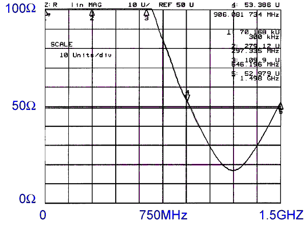
Figure 1. Input Impedance of a 1.5 GHz Active Probe With Short Connections

Address: P. O. Box 1457, Los Gatos,
CA 95031
TEL:
800-323-3956/408-356-4186
FAX:
408-358-3799
Mobile: 408-858-4528
URL:
www.dsmith.org
Email: doug@dsmith.org
Figure 1. Input Impedance of a 1.5 GHz Active Probe With Short Connections
In the April, 2001 Technical Tidbit, "Measurement Error Caused by Probe Input Impedance," factors affecting probe input impedance and calculations of possible magnitudes were discussed. This article takes the discussion one step further with measurement results on a popular 1.5 GHz active probe.
Probe frequency response is usually measured by manufacturers under ideal connections. In practical lab use, even short (1 cm and shorter) leads connecting the probe to the circuit to be measured can have dramatic effects on probe performance, especially for active probes that have a capacitive input impedance. As discussed in the April, 2001 Technical Tidbit, the inductance of probe connections results in an LC resonant circuit. The effects of such a resonant circuit can be seen in Figure 1.
Figure 1 presents the results from a network analyzer measurement of the input impedance of a popular 1.5 GHz active probe including the shortest probe tip accessory furnished with the probe. The input impedance achieves a minimum of less than 20 Ohms within the rated bandwidth of the probe! Such an input impedance is likely to have a significant effect on the circuit being measured. Both amplitude and timing errors may be introduced in the measured circuit resulting in.problems than can be either caused or "solved" upon connection of the probe to a circuit.
In addition to input impedance issues, the probe with its short connections has a significant bump in its frequency response as seen in Figure 2. Note the 7 dB gain peak at about 1 GHz. A signal at that frequency would appear to have more than double its real amplitude. Other probe connection accessories that come with many active probes are longer and make the gain peak much larger and at at lower frequencies.
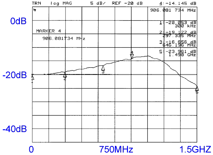
Figure 2. Frequency Response of the Probe to a 25 Ohm Source from Figure
1 with Short Connections
Most active probes are very sensitive to inductance in their connections to the circuit. Even a few cm total for both leads is too much for most probes. Many probe instruction manuals give the equivalent circuit for the probe input impedance. Take the time to do a few calculations on this circuit assuming 10 nH or so of inductance (short probing pins) in the probe connections. You may be surprised at the results. And, just because an accessory comes with a probe, do not assume it works. Many such accessories designed to connect the probe to a circuit work poorly at best.
An example of a well written probe users manual for an active probe, the Agilent 1158a, can be found at:
http://cp.literature.agilent.com/litweb/pdf/01158-97001.pdf
This users manual gives an accurate representation of probe's performance including input impedance under a wide variety of conditions. It contains good input impedance equivalent circuits and plots of impedance and frequency response for the connection hardware the comes with the probe. It addition, the probe itself contains design features I have been talking about for many years in my seminars that give it a much improved frequency response over most other active probes I have seen.
More information on this topic as well as design and troubleshooting issues in electronic circuit design and manufacturing is covered in my seminars. Click here for seminar information.