
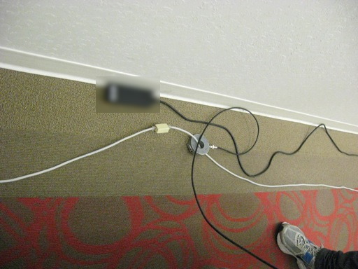
Figure 1. Setup at Middle of 30 Meter Ethernet Cable
Abstract: Power Over Ethernet
(POE) has become widespread over the last few years and with that
popularity a need has developed to add POE features to older Ethernet
hardware. As a result, POE injectors have become available which inject
DC power into an Ethernet connection. Some POE injectors significantly
unbalance the Ethernet connection which results in common mode current
on unshielded twisted pair (UTP) media. The resulting emissions from
the UTP Ethernet cable can be significant. Three POE injectors were
measured for their ability to
generate common mode currents compared to a simple coupler. The
experimental method used and results obtained are reported and contain
a surprising result.
Discussion: Anytime the paths
of an Ethernet balanced signal are disturbed, there is the possibility
of unbalancing the signal. This can be a problem for Ethernet
connecting hardware used with UTP cable that results in converting some
of the Ethernet signal into common mode currents on the cable and the associated increase of radiated emissions.
The situation is more critical for for today's higher speeds of
1000Base-T and faster. Measurements of common mode current using
three POE injectors and a simple coupler with 1000Base-T Ethernet are presented in Figures 2-5 below.
Figure 1 shows the test setup. Two UTP cables, approximately 15 meters in length, were connected to a router (that had both POE and normal ports) and an Ethernet device. The two cables were spread out along a wall in a commercial building and joined in the center with either a simple coupler or one of the three POE injectors. The coupler and one of the POE injectors can be seen in Figure 1 along with a Fischer Custom Communications F-33-1 current probe used here for measuring common mode currents. The current probe was slid along the cable to determine common mode current at points along the cable. Relatively long cables were used to reduce any contribution to the measurement from the router and Ethernet device so that the POE injectors could be more accurately compared.
Figure 2 shows the plot of common mode current for the simple coupler in Figure 1 and measured near the coupler. The red line just under 30 dBuV represents the amount of common mode current, about 5 uA, that would potentially cause an emissions problem between 30 and 100 MHz assuming dipole emission and the transfer impedance of the current probe (about 5 Ohms). The vertical scale is 10 dB/div and the horizontal scale extends from 20 MHz to 120 MHz at 10 MHz/div. Emissions measurements are usually made above 30 MHz, but I like to see what is happening just below 30 MHz as well, so the plot extends down to 20 MHz.
In Figure 2, the common mode current current above 30 MHz ranges from about 5 dB below the red line at about 35 MHz to about 20 dB below it at 120 MHz. With this profile, I would feel reasonably confident of going to formal EMC testing with an expectation of passing with a 6 dB or slightly higher margin. I do not know what the quality of the coupler was so it is possible a continuous cable without the coupler would have lower common mode currents than are shown here. One thing is sure, it was a "cheap" coupler. For this test, a POE port on the router was used to power up the Ethernet device at the opposite end of the cable. The current measurement was made using a peak detector. It is possible that the use of a Quasi-peak detector would lower the current level indicated by a few dB.
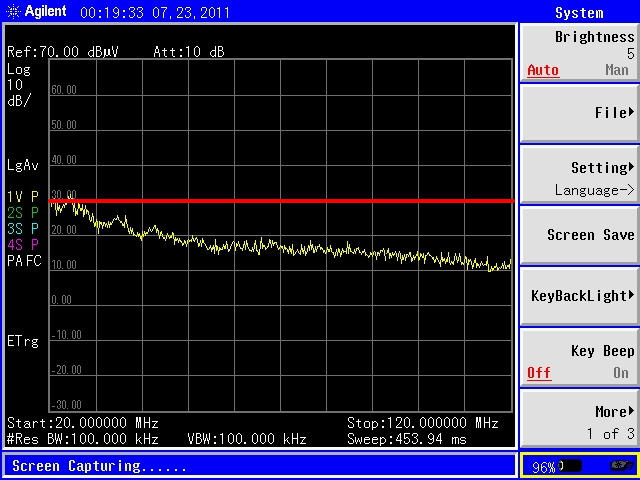
Figure 2. Measured Common Mode Current Using Coupler
(Vertical Scale = 10 dB/div, Horizontal Scale = 10 MHz/div)
In Figure 3, a POE injector bought off the shelf at a local electronics store was used to connect the two cables. Note that the common mode current is 2 to 3 dB higher below 60 MHz. This level of current would not likely cause an emissions failure but the margin would be reduced. I would still go to formal emissions testing though with this device. A non-POE port of the router was used but there was no difference if a POE port was used, however POE power from the router was not passed on to the Ethernet device through the POE injector.
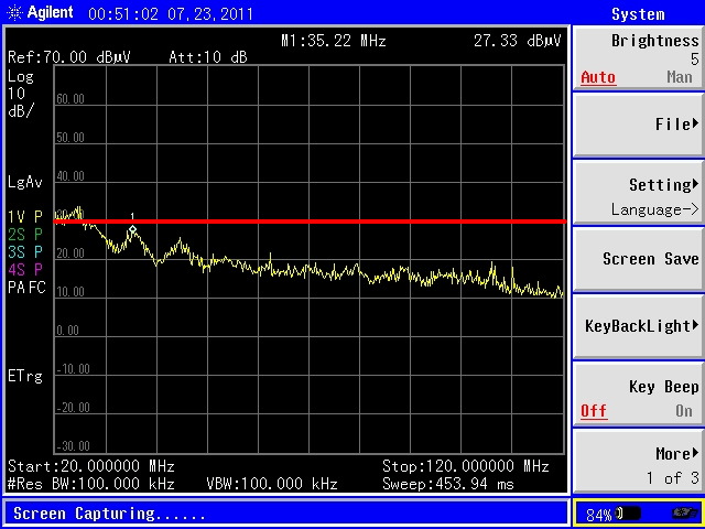
Figure 3. Measured Common Mode Current Using POE Injector 1
(Vertical Scale = 10 dB/div, Horizontal Scale = 10 MHz/div)
Figure 4 shows the common mode current plot for the second POE injector. In this case, common mode current was significantly increased below 60 MHz reaching 3 to 4 dB over the red line. The mains power was then removed from the POE and the router port was switched to a POE one. This injector would pass the router power though to the Ethernet device when the injector itself was unpowered. The plot was not significantly changed indicating that the additional common mode current was due to unbalancing the Ethernet signals and not from the POE injector power supply. I would be hesitant to go to formal emissions testing with this common mode current profile, a failure is a good possibility. If emissions testing actually passed, the margin would be very small, likely only a dB or so.
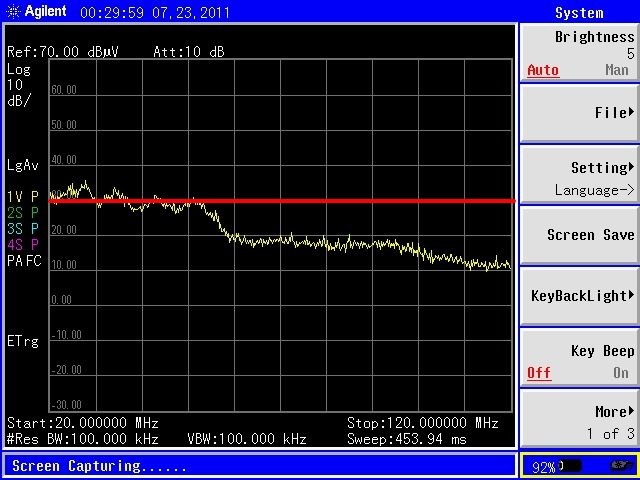
Figure 4. Measured Common Mode Current Using POE Injector 2
(Vertical Scale = 10 dB/div, Horizontal Scale = 10 MHz/div)
Figure 5 shows the common mode current generated by the third POE injector. This one generated much
more common mode current, about 14 dB higher than the coupler at around
35 MHz. This level of common mode current would most certainly generate
a radiated emissions failure. Significantly increased common mode
current can be seen up to about 70 MHz.
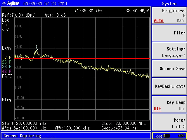
Figure 5. Measured Common Mode Current Using POE Injector 3
(Vertical Scale = 10 dB/div, Horizontal Scale = 10 MHz/div)
There was a significant variation in common mode current generation between the three POE injectors and it appears that emission failures are likely to result from some POE injectors themselves by unbalancing of the Ethernet signals. After opening the POE injectors, it was obvious in two cases that circuit board layout was a major contributor to the generation of common mode current.
Figure 1 shows the test setup. Two UTP cables, approximately 15 meters in length, were connected to a router (that had both POE and normal ports) and an Ethernet device. The two cables were spread out along a wall in a commercial building and joined in the center with either a simple coupler or one of the three POE injectors. The coupler and one of the POE injectors can be seen in Figure 1 along with a Fischer Custom Communications F-33-1 current probe used here for measuring common mode currents. The current probe was slid along the cable to determine common mode current at points along the cable. Relatively long cables were used to reduce any contribution to the measurement from the router and Ethernet device so that the POE injectors could be more accurately compared.
Figure 2 shows the plot of common mode current for the simple coupler in Figure 1 and measured near the coupler. The red line just under 30 dBuV represents the amount of common mode current, about 5 uA, that would potentially cause an emissions problem between 30 and 100 MHz assuming dipole emission and the transfer impedance of the current probe (about 5 Ohms). The vertical scale is 10 dB/div and the horizontal scale extends from 20 MHz to 120 MHz at 10 MHz/div. Emissions measurements are usually made above 30 MHz, but I like to see what is happening just below 30 MHz as well, so the plot extends down to 20 MHz.
In Figure 2, the common mode current current above 30 MHz ranges from about 5 dB below the red line at about 35 MHz to about 20 dB below it at 120 MHz. With this profile, I would feel reasonably confident of going to formal EMC testing with an expectation of passing with a 6 dB or slightly higher margin. I do not know what the quality of the coupler was so it is possible a continuous cable without the coupler would have lower common mode currents than are shown here. One thing is sure, it was a "cheap" coupler. For this test, a POE port on the router was used to power up the Ethernet device at the opposite end of the cable. The current measurement was made using a peak detector. It is possible that the use of a Quasi-peak detector would lower the current level indicated by a few dB.
Figure 2. Measured Common Mode Current Using Coupler
(Vertical Scale = 10 dB/div, Horizontal Scale = 10 MHz/div)
In Figure 3, a POE injector bought off the shelf at a local electronics store was used to connect the two cables. Note that the common mode current is 2 to 3 dB higher below 60 MHz. This level of current would not likely cause an emissions failure but the margin would be reduced. I would still go to formal emissions testing though with this device. A non-POE port of the router was used but there was no difference if a POE port was used, however POE power from the router was not passed on to the Ethernet device through the POE injector.
Figure 3. Measured Common Mode Current Using POE Injector 1
(Vertical Scale = 10 dB/div, Horizontal Scale = 10 MHz/div)
Figure 4 shows the common mode current plot for the second POE injector. In this case, common mode current was significantly increased below 60 MHz reaching 3 to 4 dB over the red line. The mains power was then removed from the POE and the router port was switched to a POE one. This injector would pass the router power though to the Ethernet device when the injector itself was unpowered. The plot was not significantly changed indicating that the additional common mode current was due to unbalancing the Ethernet signals and not from the POE injector power supply. I would be hesitant to go to formal emissions testing with this common mode current profile, a failure is a good possibility. If emissions testing actually passed, the margin would be very small, likely only a dB or so.
Figure 4. Measured Common Mode Current Using POE Injector 2
(Vertical Scale = 10 dB/div, Horizontal Scale = 10 MHz/div)
Figure 5. Measured Common Mode Current Using POE Injector 3
(Vertical Scale = 10 dB/div, Horizontal Scale = 10 MHz/div)
There was a significant variation in common mode current generation between the three POE injectors and it appears that emission failures are likely to result from some POE injectors themselves by unbalancing of the Ethernet signals. After opening the POE injectors, it was obvious in two cases that circuit board layout was a major contributor to the generation of common mode current.
Summary: Some POE
injectors have the ability to generate enough common mode current to
result in radiated emissions failures due to unbalancing the Ethernet
signals. Be sure to qualify any POE injectors you intend to use with
your system separately from the system to make sure you have not picked one that will cause radiated emissions problems.
Additional articles on this website related to this topic are:
- Current Probes, More Useful Than You Think (~170K)
- (1998 IEEE EMC Symposium paper)
- March 2006, Predicting Cable Emissions from Common Mode Current
Need help with a design or additional training on technical subjects? Click on the image below to go to CircuitAdvisor.com, a new engineering resource for training, news, and fun.

If you like the information in this article and others on this website,
much more information is available in my courses. Click here
to see a listing of upcoming courses on design, measurement, and
troubleshooting of chips, circuits, and systems. Click here to see upcoming seminars in Newport Beach, CA.
Click here for a description of my latest seminar titled (now also available online as a WebEx seminar):
EMC
Lab Techniques for Designers
(How to find EMC problems and have some confidence your system will pass EMC testing while it is still in your lab).
(How to find EMC problems and have some confidence your system will pass EMC testing while it is still in your lab).
Home