
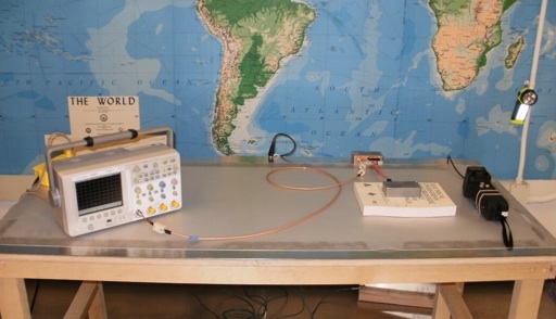
Figure 1. Test Setup For Measuring ESD Induced Voltage in SATA Cables
Abstract: The results of an investigation into the shielding
effectiveness of SATA (serial ATA) cables used with modern disk drives
are presented. The voltages induced into several SATA cables from an
ESD stress are reported and conclusions drawn.
Discussion: Figure 1 shows the
overall test setup. The test was conducted on the surface of an ESD table
that meets IEC 61000-4-2. The simulator ground was returned to the
table top metal plane ("Horizontal Coupling Plane") instead of the
"Reference Ground Plane" on the floor to maximize low frequency currents flowing as
a result of the ESD stress. All measurements were taken using a 500
Volt setting of the ESD simulator.
The test apparatus consisted of two metal boxes connected by the SATA cable under test. In the measurement box, the shield of the SATA cable was connected in a very direct manner to the metal box and all of the signal wires were tied together and connected to the center pin of a BNC connector. Details are shown in Figure 2. An RG-142B/U coaxial cable connected the measurement box to the oscilloscope. Several ferrite cores were placed along this cable to help prevent ESD induced noise from affecting the scope. The measurement box was securely tied to the metal plane on the table by copper EMI tape.
The termination box also had the SATA cable shield connected as directly as possible to the metal box but in addition so were the signal wires. This box was placed on a book and ESD was applied to the outside of the box. The box was raised up by the book to minimize coupling of high frequency energy directly into the metal plane, which would make the cable look better than it actually was as much of the ESD current would couple directly through capacitance into the plane and not flow down the cable if the box were place directly on the insulating sheet on the metal plane. Figure 3 shows a view of the inside of the termination box.
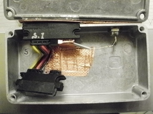
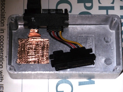
Figure 3. Inside View of Termination Box
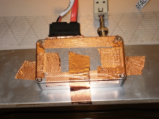
Figure 4 shows a close-up view of the measurement box as well as the copper EMI tape sealing it and connecting it to the metal plane on the table. One of the ferrite cores on the coaxial cable connecting the box to the scope is also visible.
The test was conducted with a variety of short (one foot, 30 cm) and long (> two feet, 60 cm) SATA cables. A close-up of the test setup for one of the longer SATA cables is shown in Figure 5. Note the copper EMI tape used to seal both boxes and connect the measurement box to the metal plane on the table.
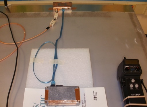
Figure 5. Test Setup with Longer SATA Cable
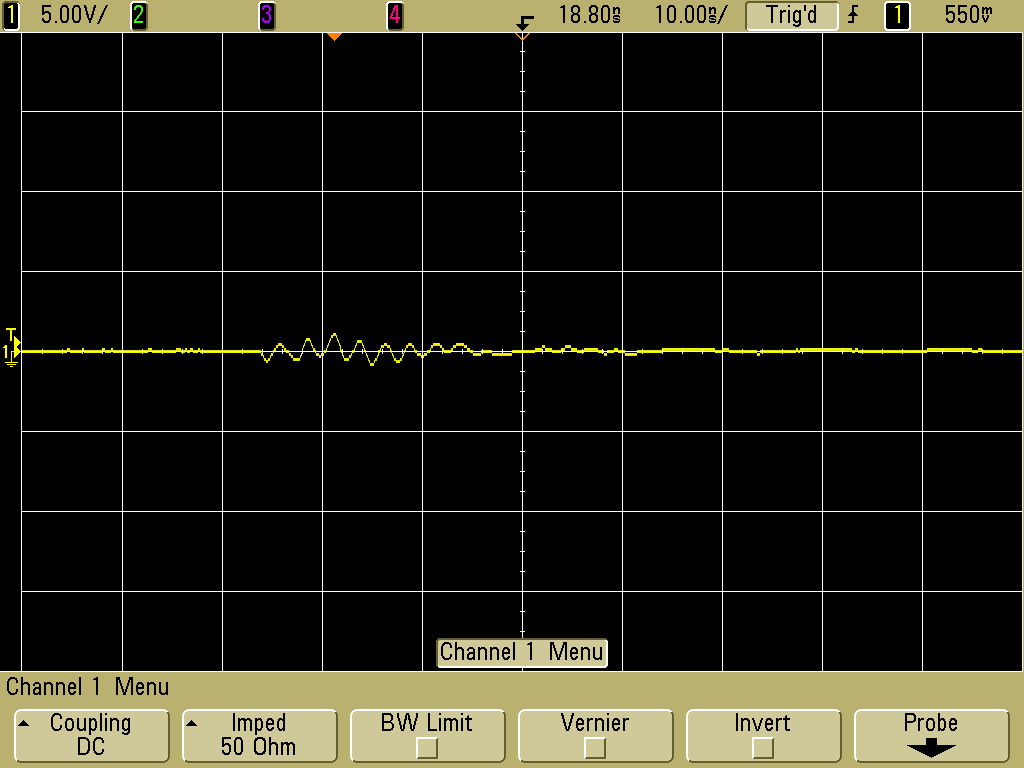
Figure 6 shows the signal measured at the measurement box when the simulator was discharged directly into the metal plane near the measurement box. This was done to check for leakage of ESD noise into the measurement box. I call this a "null experiment." The peak noise recorded was about one Volt.
Figures 7 and 8 show results for two SATA cables although the cable in Figure 8 was somewhat longer. The important point to note is the peak voltage between the signal wires and the shield was over 10 Volts in both cases! This is not good for only 500 Volt ESD and is likely due to the plastic connectors used requiring the shield to be connected through the pins of the connector at each end of the cable.
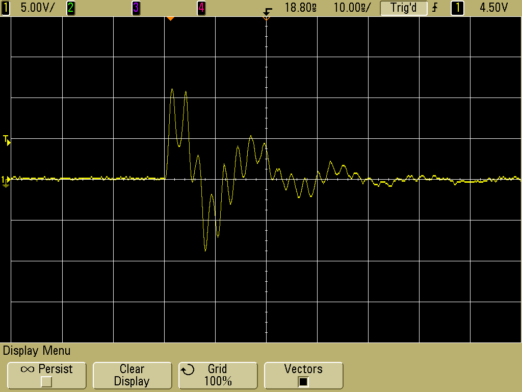
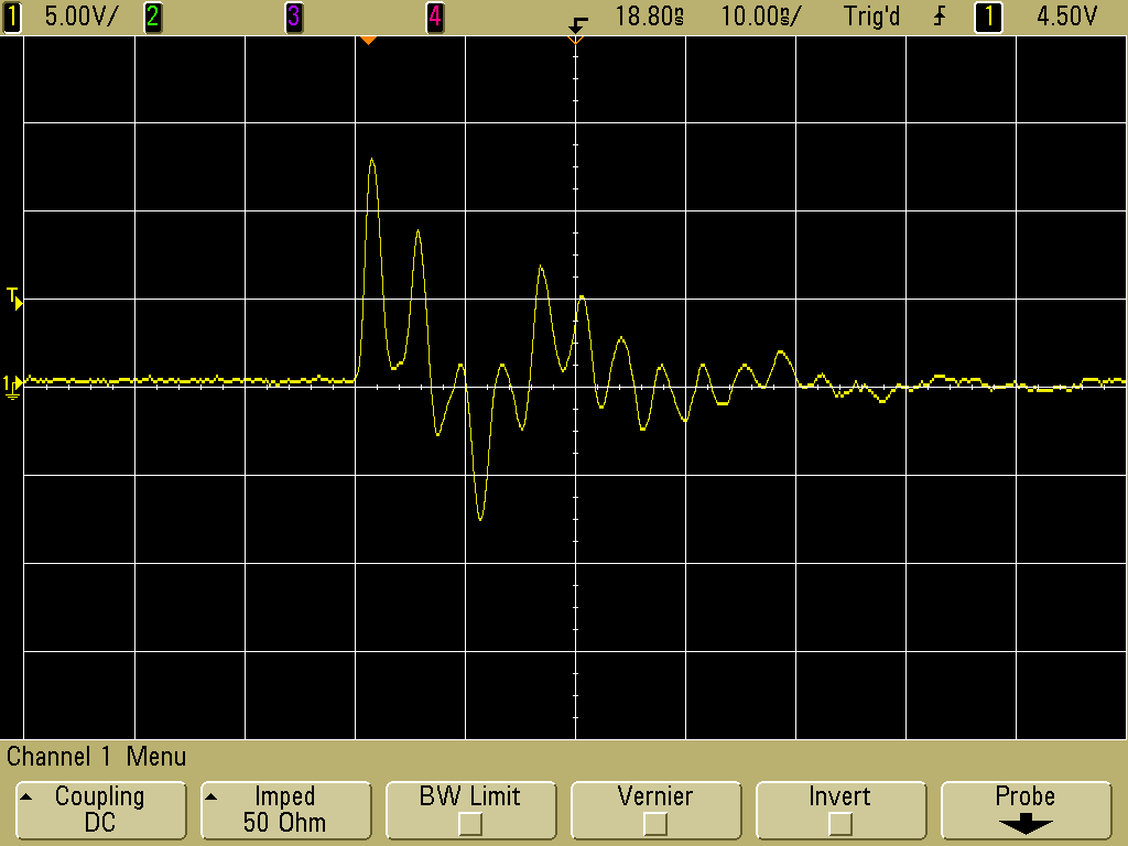
Figure 9 shows the results for a much longer cable. If the shielding was limited by the cable, one might expect a higher amplitude, but a lower amplitude resulted. The longer cable lowers the current that was flowing because of increased inductance and this lowers the drop across the shield connections in the connectors (shield transfer impedance of the connector pairs). Still, six Volts peak ESD noise from a 500 Volt discharge is not good for a cable.
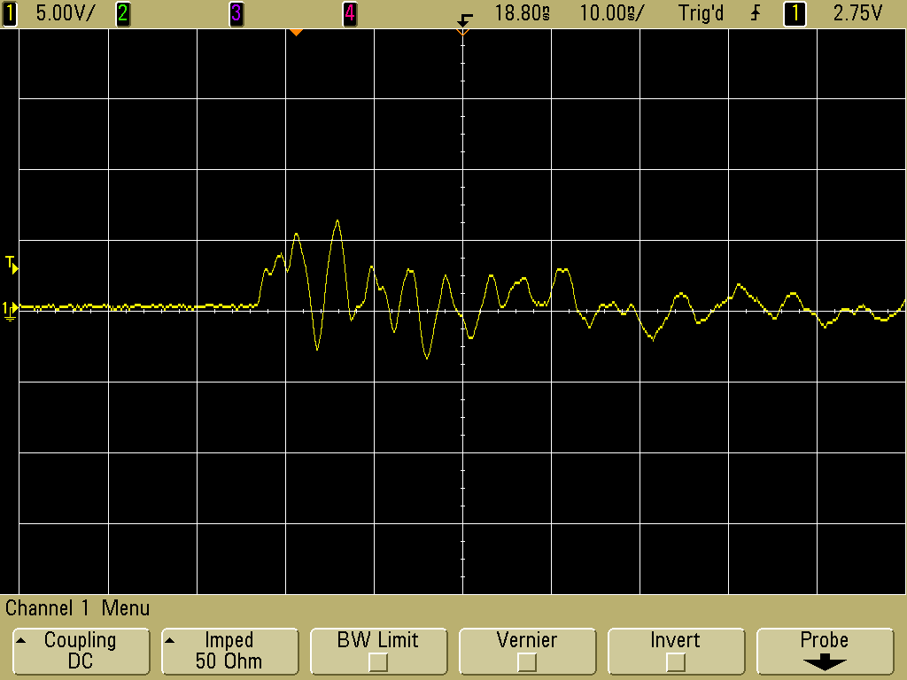
Figure 9. Measured Voltage For a Long (>24 inches, 60 cm) SATA Cable
(Vertical scale = 5 V/div, Horizontal scale = 10 ns/div)
The ESD induced noise in this experiment can easily corrupt data being transmitted on the SATA cables especially when one considers the fact than only 500 Volt contact discharges were used, about 1/8 of the amplitude used in general CE Mark testing. Either data errors or delays in transmission may result. Also consider that the scope had a 500 MHz bandwidth. If a higher bandwidth scope was used, the peak amplitudes might be somewhat larger considering the ESD stress had a risetime of around 300 to 500 ps.
In my opinion, cables and connectors like these should not be used outside of shielded enclosures if ESD induced errors ares not allowed.
Summary:
ESD stress was applied to typical SATA cables of a few different
manufacturers. In all cases, the amount of ESD noise present on the
signal wires was high enough to cause signal corruption for only 500
Volt ESD! In my opinion, cables and connectors like these should not be used
outside of shielded enclosures if ESD induced errors ares not allowed.
The test apparatus consisted of two metal boxes connected by the SATA cable under test. In the measurement box, the shield of the SATA cable was connected in a very direct manner to the metal box and all of the signal wires were tied together and connected to the center pin of a BNC connector. Details are shown in Figure 2. An RG-142B/U coaxial cable connected the measurement box to the oscilloscope. Several ferrite cores were placed along this cable to help prevent ESD induced noise from affecting the scope. The measurement box was securely tied to the metal plane on the table by copper EMI tape.
The termination box also had the SATA cable shield connected as directly as possible to the metal box but in addition so were the signal wires. This box was placed on a book and ESD was applied to the outside of the box. The box was raised up by the book to minimize coupling of high frequency energy directly into the metal plane, which would make the cable look better than it actually was as much of the ESD current would couple directly through capacitance into the plane and not flow down the cable if the box were place directly on the insulating sheet on the metal plane. Figure 3 shows a view of the inside of the termination box.
Figure 2. Inside View of Measurement Box
Figure 3. Inside View of Termination Box
Figure 4 shows a close-up view of the measurement box as well as the copper EMI tape sealing it and connecting it to the metal plane on the table. One of the ferrite cores on the coaxial cable connecting the box to the scope is also visible.
Figure 4. Measurement Box Mounting with Copper Shielding Tape
The test was conducted with a variety of short (one foot, 30 cm) and long (> two feet, 60 cm) SATA cables. A close-up of the test setup for one of the longer SATA cables is shown in Figure 5. Note the copper EMI tape used to seal both boxes and connect the measurement box to the metal plane on the table.
Figure 5. Test Setup with Longer SATA Cable
Figure 6 shows the signal measured at the measurement box when the simulator was discharged directly into the metal plane near the measurement box. This was done to check for leakage of ESD noise into the measurement box. I call this a "null experiment." The peak noise recorded was about one Volt.
Figure 6. Measured Voltage in Null Experiment (Discharge to Metal Plane near Measurement Box
(Vertical scale = 5 V/div, Horizontal scale = 10 ns/div)
(Vertical scale = 5 V/div, Horizontal scale = 10 ns/div)
Figures 7 and 8 show results for two SATA cables although the cable in Figure 8 was somewhat longer. The important point to note is the peak voltage between the signal wires and the shield was over 10 Volts in both cases! This is not good for only 500 Volt ESD and is likely due to the plastic connectors used requiring the shield to be connected through the pins of the connector at each end of the cable.
Figure 7. Measured Voltage For a Short (~9 inch) SATA Cable
(Vertical scale = 5 V/div, Horizontal scale = 10 ns/div)
(Vertical scale = 5 V/div, Horizontal scale = 10 ns/div)
Figure 8. Measured Voltage For Another SATA Cable
(Vertical scale = 5 V/div, Horizontal scale = 10 ns/div)
(Vertical scale = 5 V/div, Horizontal scale = 10 ns/div)
Figure 9 shows the results for a much longer cable. If the shielding was limited by the cable, one might expect a higher amplitude, but a lower amplitude resulted. The longer cable lowers the current that was flowing because of increased inductance and this lowers the drop across the shield connections in the connectors (shield transfer impedance of the connector pairs). Still, six Volts peak ESD noise from a 500 Volt discharge is not good for a cable.
Figure 9. Measured Voltage For a Long (>24 inches, 60 cm) SATA Cable
(Vertical scale = 5 V/div, Horizontal scale = 10 ns/div)
The ESD induced noise in this experiment can easily corrupt data being transmitted on the SATA cables especially when one considers the fact than only 500 Volt contact discharges were used, about 1/8 of the amplitude used in general CE Mark testing. Either data errors or delays in transmission may result. Also consider that the scope had a 500 MHz bandwidth. If a higher bandwidth scope was used, the peak amplitudes might be somewhat larger considering the ESD stress had a risetime of around 300 to 500 ps.
In my opinion, cables and connectors like these should not be used outside of shielded enclosures if ESD induced errors ares not allowed.
I would like to thank RMV Technology Group at NASA Ames Research Center for use of their facilities to generate the data for this Technical Tidbit.
Additional articles on this website related to this topic are:
Equipment used in this Technical Tidbit:
- Agilent DSO5054A, a great little scope that is easy to use and boots in 9 seconds flat!
- KeyTek MZ-15 ESD Simulator
Need help with a design or additional training on technical subjects? Click on the image below to go to CircuitAdvisor.com, a new engineering resource for training, news, and fun.
If you like the information in this article and others on this website,
much more information is available in my courses. Click here
to see a listing of upcoming courses on design, measurement, and
troubleshooting of chips, circuits, and systems. Click here to see upcoming seminars in Newport Beach, CA.
Click here for a description of my latest seminar titled (now also available online as a WebEx seminar):
EMC
Lab Techniques for Designers
(How to find EMC problems and have some confidence your system will pass EMC testing while it is still in your lab).
(How to find EMC problems and have some confidence your system will pass EMC testing while it is still in your lab).
Home