
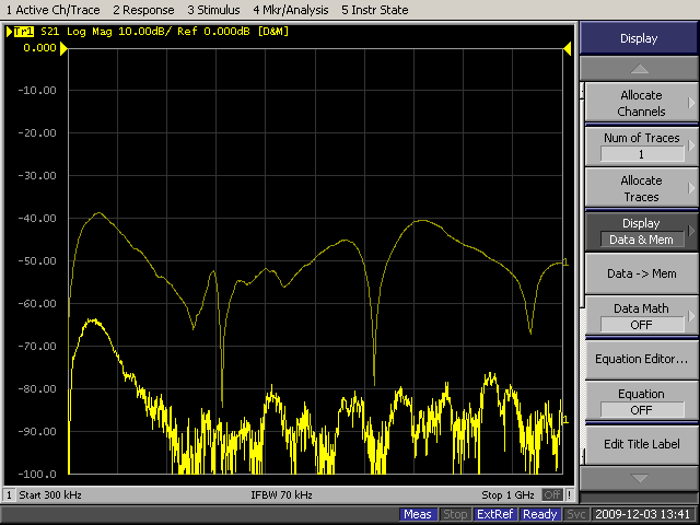
Figure 1. Measured Currents Generated by the IEEE Std 802.3™-2002 Annex 40B Coupling Clamp
(10 dB/div, 300 kHz to 1 GHz for ~100 MHz/div)
Abstract: An injection clamp
is defined in IEEE Std 802.3™-2002 Annex 40B for testing conducted
immunity on 1000Base-T Ethernet ports. There has been a move to use
that clamp for conducted immunity testing of 10GBase-T Ethernet ports as well. However, the clamp has significant
problems when used at frequencies above 300 MHz and should not be used
for these higher frequencies. A few other problems that can result
from using this clamp for 10GBase-T port immunity testing are also discussed.
Discussion: Figure 1
shows a plot of the current measured at both ends of the injection
clamp defined in IEEE Std 802.3™-2002 Annex 40B which is shown in
Figure 2. The clamp and its connection to a test board are
shown. Although the Fischer F-65 current probe is shown positioned next
to the test board, in fact it was placed as close as possible to the right end
of the clamp to generate the data in Figure 1.
Looking at the top trace of Figure 1, one can see three well defined resonances due to the injection clamp at about 310 MHz, 620 MHz, and 930 MHz. The resonances were in the clamp, not in the test setup. Note that up to 250 MHz, the upper frequency used for 1000Base-T Ethernet testing, the injected current supplied to the test board is well behaved. The downward slope is likely due to the inductance of the 20 cm cable between the clamp and the test board. For 10GBase-T Ethernet testing, the clamp is being used up to 1000 MHz. Taking into consideration the data shown in Figure 1, this is probably not a good idea.
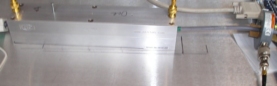
Figure 2. Current Probe Placement on the Test Board Side of Clamp
Figure 3 shows ferrite cores on the 10GBase-T Ethernet cable on the opposite side of the clamp. IEEE Std 802.3™-2002 Annex 40B calls for just two ferrite cores here. I do not believe one can achieve enough isolation between the uncontrolled common mode world over a bandwidth all the way to one GHz with just two cores. Lab experience bears this out as touching the cable to the left of only two cores, in one test, significantly changed the current plot of Figure 1.
Figure 3 shows a solution, 11 ferrite cores comprised out of a mixture of low and high frequency cores arranged in a non-repeating pattern. When the current probe was positioned shown in Figure 3, the bottom trace of Figure 1 results. The lower trace is near the noise floor of the analyzer at many frequencies. The ratio between the two traces is 20+ dB, enough to insure adequate isolation of the uncontrolled common mode environment past the ferrites, so that common mode variations do not significantly affect the current delivered to the test board or EUT. The 11 ferrites used here seem to be the minimum needed unless much better ferrite cores can be found. For the case of just two high frequency ferrites, the two plots of Figure 1 do not show much separation, especially below 500 MHz.
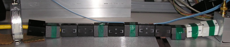
Figure 3. Current Probe Placement on Opposite Side of Clamp From TEst Board
An additional problem
may exist as well at the high end of the frequency range used for conducted
immunity testing of 10GBase-T Ethernet ports. The problem is caused by the clamp which ends abruptly and
may capacitively couple more to one wire of a twisted pair than the other wire of the same pair. This
seemed to be happening during this test. When the clamp was moved about
1/2 cm, comparable a twist length of the pairs in the cable (the twist lengths are
all slightly different to minimize crosstalk), a difference was seen on some pairs in the
resulting differential mode interference. This effect needs to be more
thoroughly investigated.
Looking at the top trace of Figure 1, one can see three well defined resonances due to the injection clamp at about 310 MHz, 620 MHz, and 930 MHz. The resonances were in the clamp, not in the test setup. Note that up to 250 MHz, the upper frequency used for 1000Base-T Ethernet testing, the injected current supplied to the test board is well behaved. The downward slope is likely due to the inductance of the 20 cm cable between the clamp and the test board. For 10GBase-T Ethernet testing, the clamp is being used up to 1000 MHz. Taking into consideration the data shown in Figure 1, this is probably not a good idea.
Figure 2. Current Probe Placement on the Test Board Side of Clamp
Figure 3 shows ferrite cores on the 10GBase-T Ethernet cable on the opposite side of the clamp. IEEE Std 802.3™-2002 Annex 40B calls for just two ferrite cores here. I do not believe one can achieve enough isolation between the uncontrolled common mode world over a bandwidth all the way to one GHz with just two cores. Lab experience bears this out as touching the cable to the left of only two cores, in one test, significantly changed the current plot of Figure 1.
Figure 3 shows a solution, 11 ferrite cores comprised out of a mixture of low and high frequency cores arranged in a non-repeating pattern. When the current probe was positioned shown in Figure 3, the bottom trace of Figure 1 results. The lower trace is near the noise floor of the analyzer at many frequencies. The ratio between the two traces is 20+ dB, enough to insure adequate isolation of the uncontrolled common mode environment past the ferrites, so that common mode variations do not significantly affect the current delivered to the test board or EUT. The 11 ferrites used here seem to be the minimum needed unless much better ferrite cores can be found. For the case of just two high frequency ferrites, the two plots of Figure 1 do not show much separation, especially below 500 MHz.
Figure 3. Current Probe Placement on Opposite Side of Clamp From TEst Board
Summary: The data presented shows that the coupling clamp used in IEEE
Std 802.3™-2002 Annex 40B has significant resonances above 300 MHz and
should not be used to test conducted immunity on 10GBase-T Ethernet ports.
In addition, two
ferrites are not likely to provide adequate isolation of the test from
the external common mode world. A mixture of 11 high and low frequency
ferrites yielded adequate isolation. The shape of the clamp itself may
be causing unbalance on some pairs, an effect that needs additional
investigation.
Additional articles on this website related to this topic are: Equipment used for this article:
If you like the information in this article and others on this website, much more information is available in my courses. Click here to see a listing of upcoming courses on design, measurement, and troubleshooting of chips, circuits, and systems. Click here to see upcoming seminars in Newport Beach, CA.
Click here for a description of my latest seminar titled (now also available online as a WebEx seminar).
EMC
Lab Techniques for Designers
(How to find EMC problems and have some confidence your system will pass EMC testing while it is still in your lab).
(How to find EMC problems and have some confidence your system will pass EMC testing while it is still in your lab).
 |
My new website for engineers and technicians, CircuitAdvisor.com, is coming! The site will contain technews and analysis programs, cartoons, multimedia tutorials and more.The site will be open soon. |
Home