
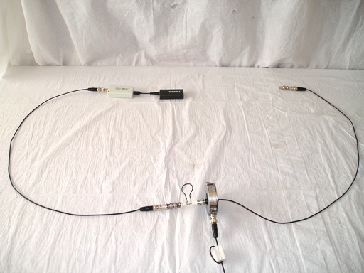
Figure 1. Test Setup with USB Powered Comb Generator, Current Probe, and Cable
Abstract: A comb generator RF source can be a handy substitute when a
tracking generator is not available on a spectrum analyzer.
In
this case, a USB powered comb generator RF source is used to
supply the signal in order to measure impairment of the shielding
effectiveness in a coaxial
cable. This is a useful demonstration when trying to convince others of
the problems caused by using a pigtail lead connection of a cable
shield.
Discussion: Figure 1
shows an AET USB-S-1.84 RF Source comb generator (so called
because its frequency spectrum looks like a comb on the display of a
spectrum analyzer) feeding one end of a pair of 1.5 meter coaxial
cables (RG174/U) joined by a fixture that connects the shields of the
two cables with a wire (sometimes called a "pigtail"). The other end of
the pair of coaxial cables, on the right opposite the comb generator,
is terminated with a 50 Ohm coaxial termination.
Using pigtail connections to the shield of a cable is known to seriously reduce the shielding effectiveness of the shield. To show this effect, it would be desirable to use a tracking generator built into a spectrum analyzer, but what if one is not available? In this case, I will show that using a small comb generator RF source can replace the tracking generator. An advantage of using the comb generator is that it is small and will have a minimal effect on the results compared to the chassis of a spectrum analyzer which will significantly change the resonant frequencies of the cables used for this experiment.
Figure 2 shows the comb generator connected directly to the spectrum analyzer through a one meter coaxial cable while Figure 3 shows the spectrum plot that results. This comb generator has a low fundamental frequency of 1.84 MHz and so produces closely spaced harmonics over the 200 MHz frequency span displayed.
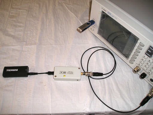
Figure 2. Test Setup With Comb Generator and Spectrum Analyzer
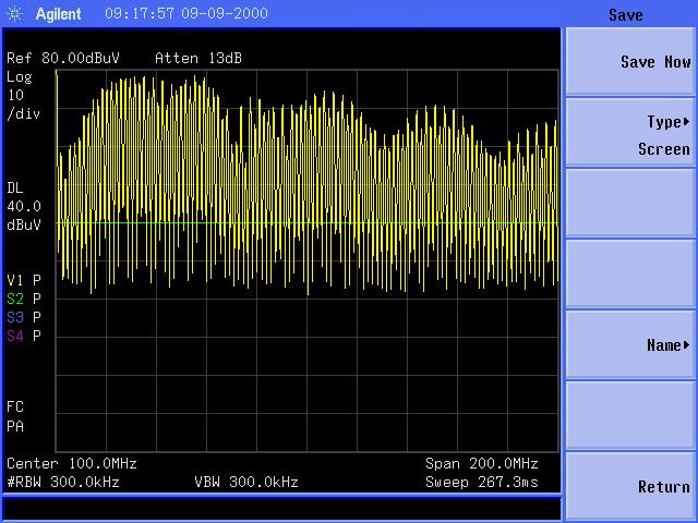
Figure 3. Frequency Spectrum of Comb Generator Output
(Vertical Scale = 10 dB/div, Horizontal Scale = 20 MHz/div)
Figure 4 shows the two cables of Figure 1 joined by a BNC barrel resulting in a continuous 360 degree shield through the junction. The common mode current on the shield measured by the Fischer F-33-1 Current probe appears in Figure 5. The plot was unaffected by whether the comb generator was powered or not. The spikes noted on the display were from radio signals in the area, with those at the center of the plot being from local FM broadcast stations. There was no visible evidence of the signal from the comb generator, as expected.
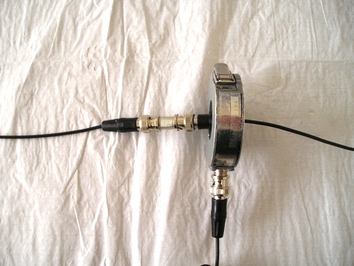
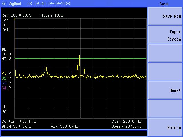
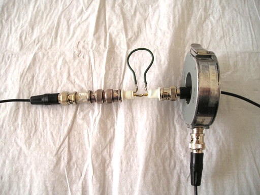
Figure 6. Shield Connection Made Using 8 cm Pigtail
Note that the harmonics of the comb generator have major peaks near 50 MHz and again near 150 MHz. At these frequencies, the RF voltage developed across the pigtail can drive current on the outside of the cable shields, using the shields as a dipole antenna. A similar measurement using a second current probe and a tracking generator in the spectrum analyzer is described in the January 20008 Technical Tidbit on this site. That measurement shows cable resonances like the two in Figure 7. However the comb generator driven measurement is accomplished at a significantly lower cost by not requiring the tracking generator or second current probe.
The horizontal green line on the spectrum analyzer is set approximately at a current level that would cause a class A industrial device to just hit the CISPR emissions limit if that current were fed to a dipole. Note that several harmonics of the comb generator exceed this level around the two peaks at about 50 and 150 MHz. The result would be a failure of emissions requirements for Class A by several dB and of Class B requirements (10 dB lower) by many dB. This simple experiment shows a major problem that can result if shields are connected with pigtails.
An interesting point is that the low fundamental frequency of the comb generator, 1.84 MHz, produce closely space harmonics that show the two cable resonances near 50 and 150 MHz. If the comb generator had a higher fundamental frequency, that frequency and its harmonics may have missed the two cable resonances altogether and no emissions problem would have resulted. A low frequency signal with a fast risetime, 300 ps in this case, can be more dangerous that a higher frequency signal!
I would like to encourage readers of this site to use simple experiments like this one, others on this site, and ones of the readers' design to increase the strength of their engineering viewpoints with your colleagues. A little data can help you make your point in project meetings!
Using pigtail connections to the shield of a cable is known to seriously reduce the shielding effectiveness of the shield. To show this effect, it would be desirable to use a tracking generator built into a spectrum analyzer, but what if one is not available? In this case, I will show that using a small comb generator RF source can replace the tracking generator. An advantage of using the comb generator is that it is small and will have a minimal effect on the results compared to the chassis of a spectrum analyzer which will significantly change the resonant frequencies of the cables used for this experiment.
Figure 2 shows the comb generator connected directly to the spectrum analyzer through a one meter coaxial cable while Figure 3 shows the spectrum plot that results. This comb generator has a low fundamental frequency of 1.84 MHz and so produces closely spaced harmonics over the 200 MHz frequency span displayed.
Figure 2. Test Setup With Comb Generator and Spectrum Analyzer
Figure 3. Frequency Spectrum of Comb Generator Output
(Vertical Scale = 10 dB/div, Horizontal Scale = 20 MHz/div)
Figure 4 shows the two cables of Figure 1 joined by a BNC barrel resulting in a continuous 360 degree shield through the junction. The common mode current on the shield measured by the Fischer F-33-1 Current probe appears in Figure 5. The plot was unaffected by whether the comb generator was powered or not. The spikes noted on the display were from radio signals in the area, with those at the center of the plot being from local FM broadcast stations. There was no visible evidence of the signal from the comb generator, as expected.
Figure 4. Shield Connection Made Using BNC Barrel
Figure 5. Plot of Common Mode Current With Shield Connection Made Using BNC Barrel
(Vertical Scale = 10 dB/div, Horizontal Scale = 20 MHz/div)
(Vertical Scale = 10 dB/div, Horizontal Scale = 20 MHz/div)
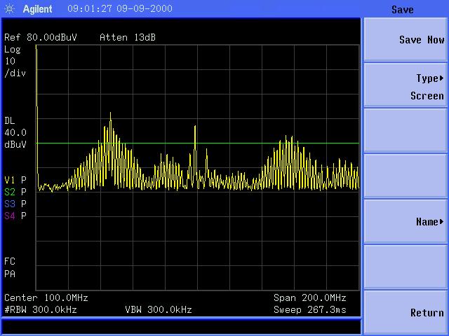
Figure 6 shows the two cables joined
by the pigtail wire as also shown in Figure 1. The resulting common
mode current is displayed in Figure 7. Note that many harmonics of the comb
generator are now visible on the display.
Figure 6. Shield Connection Made Using 8 cm Pigtail
Figure 7. Plot of Common Mode Current With Shield Connection Made Using 8 cm Pigtail
(Vertical Scale = 10 dB/div, Horizontal Scale = 20 MHz/div)
(Vertical Scale = 10 dB/div, Horizontal Scale = 20 MHz/div)
Note that the harmonics of the comb generator have major peaks near 50 MHz and again near 150 MHz. At these frequencies, the RF voltage developed across the pigtail can drive current on the outside of the cable shields, using the shields as a dipole antenna. A similar measurement using a second current probe and a tracking generator in the spectrum analyzer is described in the January 20008 Technical Tidbit on this site. That measurement shows cable resonances like the two in Figure 7. However the comb generator driven measurement is accomplished at a significantly lower cost by not requiring the tracking generator or second current probe.
The horizontal green line on the spectrum analyzer is set approximately at a current level that would cause a class A industrial device to just hit the CISPR emissions limit if that current were fed to a dipole. Note that several harmonics of the comb generator exceed this level around the two peaks at about 50 and 150 MHz. The result would be a failure of emissions requirements for Class A by several dB and of Class B requirements (10 dB lower) by many dB. This simple experiment shows a major problem that can result if shields are connected with pigtails.
An interesting point is that the low fundamental frequency of the comb generator, 1.84 MHz, produce closely space harmonics that show the two cable resonances near 50 and 150 MHz. If the comb generator had a higher fundamental frequency, that frequency and its harmonics may have missed the two cable resonances altogether and no emissions problem would have resulted. A low frequency signal with a fast risetime, 300 ps in this case, can be more dangerous that a higher frequency signal!
I would like to encourage readers of this site to use simple experiments like this one, others on this site, and ones of the readers' design to increase the strength of their engineering viewpoints with your colleagues. A little data can help you make your point in project meetings!
Summary:
A small comb generator RF source can be used instead of an expensive
tracking generator for some EMC measurements. The case of a pigtail
wire connecting cable shields was used to illustrate a common EMC
design problem and to show one such possible use of a comb generator.
Simple experiments like this one can often help engineers get their
points across to others.
Additional articles on this website related to this topic are:
- March 2006, Predicting Cable Emissions from Common Mode Current
- January 2008, Using Current Probes to Measure Cable Resonance
(Current Probes, More Useful Than You Think - Part 3) - August 2009, The Square Shielded Loop - Part 6, Measurements in the Time Domain Using a Comb Generator
(An unusual use for a comb generator) - September 2009, Using a Two AA Cell USB Charger to Power a Comb Generator
(A Handy Power Soure for Any USB Powered Device)
- USB powered Comb Generator
- Agilent N9320B Spectrum Analyzer
- Fischer Custom Communications F-33-1 Current Probe
If you like the information in this article and others on this website, much more information is available in my courses. Click here to see a listing of upcoming courses on design, measurement, and troubleshooting of chips, circuits, and systems. Click here to see upcoming seminars in Newport Beach, CA.
Click here for a description of my latest seminar titled (now also available online as a WebEx seminar):
EMC
Lab Techniques for Designers
(How to find EMC problems and have some confidence your system will pass EMC testing while it is still in your lab).
(How to find EMC problems and have some confidence your system will pass EMC testing while it is still in your lab).
 |
My new website for engineers and technicians, CircuitAdvisor.com, is coming! The site will contain technews and analysis programs, cartoons, multimedia tutorials and more.The site will be open soon. |
Home