
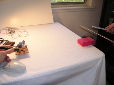
Figure 1. Test Setup
Abstract: Passive differential
probes perform very well in the presence of severe EMI. Data is
presented to compare the noise immunity of a standard unbalanced 50 Ohm
resistive probe to a passive differential probe. The
performance of the passive differential probe is shown to be much
better.
Discussion: Figure 1 shows the test setup used. A probe is used to measure the output of an oscillator in the presence of ESD generated noise from a static driven spark gap.
The spark gap EMI source is about 40 cm from the oscillator
output. A close-up of a standard 50 Ohm 10:1 resistive
divider probe with a one gigahertz bandwidth connected to the oscillator is shown in Figure 2. A
short piece of wire is used in the BNC connector so that the probe can
clip onto the oscillator signal. Although the wire protrudes about one
cm above the probe, this is very small compared to the dimensions of
the probe an its ground lead so the antenna effect would be small. The
complete unbalanced probe can be seen in the upper left of Figure 1.
EMI gets into the measurement using the unbalanced 50 Ohm probe in two ways. The probe and its ground lead form a loop that can pickup EMI. In addition, the EMI sets up current on the probe cable which flows on the ground lead of the probe and generates a voltage drop across that appears as an input to the probe. The further the EMI source is from the probe, the less important the loop becomes and the more important the current flowing on the probe cable becomes for generating noise in the measurement.
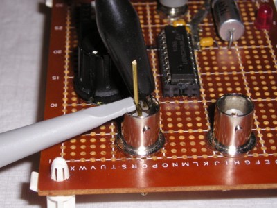
Figure 3 shows a close-up of the connection of a passive differential probe to the oscillator. Since this probe has a bandwidth of almost 2 GHz, its probe tips are small. The small probe tips contribute to keeping the measurement loop small and therefore the induced noise from the EMI small due to the measurement loop. The excellent active differential probes on the market also have small probe tips, but they do not have high enough common mode range to work under severe EMI conditions.
EMI gets into the measurement using the unbalanced 50 Ohm probe in two ways. The probe and its ground lead form a loop that can pickup EMI. In addition, the EMI sets up current on the probe cable which flows on the ground lead of the probe and generates a voltage drop across that appears as an input to the probe. The further the EMI source is from the probe, the less important the loop becomes and the more important the current flowing on the probe cable becomes for generating noise in the measurement.
Figure 2. Connection of Resistive Divider Probe to the Oscillator
Figure 3 shows a close-up of the connection of a passive differential probe to the oscillator. Since this probe has a bandwidth of almost 2 GHz, its probe tips are small. The small probe tips contribute to keeping the measurement loop small and therefore the induced noise from the EMI small due to the measurement loop. The excellent active differential probes on the market also have small probe tips, but they do not have high enough common mode range to work under severe EMI conditions.
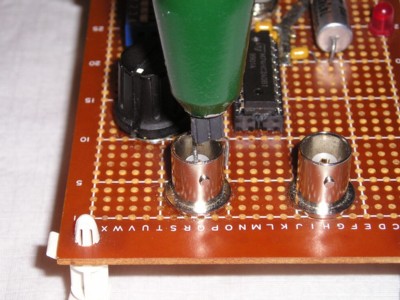
Figure 3. Connection of Passive Differential Probe to the Oscillator
Figure 4 shows the result of
measuring a 20 MHz square wave using the 50 Ohm resistive divider
probe. Note that the interference from the spark gap EMI source is
greater than 16 Volts peak-to-peak, much larger than the 4 to 5 Volt
squarewave! After the initial spike, the effects of the EMI continue
for over 60 nanoseconds.
Figure 4. Probe Output With One Pin Touching Metal Plate - ~Common Mode Signal
(Vertical scale = 2 Volts/div, Horizontal scale = 20 ns/div)
(Vertical scale = 2 Volts/div, Horizontal scale = 20 ns/div)
Figure 5 shows the measured result
using the passive differential probe. The EMI is much lower, being only
2 Volts peak-to-peak. And, this amount of noise is more likely due to wiring
in the oscillator than the probe performance. Figure 6 shows the underside of the
oscillator with its 3 to 4 cm connections to the BNC connectors. This
wiring is likely limiting the effectiveness of the differential probe
by providing an antenna for the EMI. If the oscillator were in a metal
box. the EMI in Figure 5 would likely be much lower.
There is a slight droop in the square wave of Figure 5. This is due to the low frequency rolloff of the passive differential probe, which is AC coupled.
There is a slight droop in the square wave of Figure 5. This is due to the low frequency rolloff of the passive differential probe, which is AC coupled.
Figure 5. Probe Output With Two Pins Touching Metal Plate - Differential Signal
(Vertical scale = 2 Volts/div, Horizontal scale = 20 ns/div)
(Vertical scale = 2 Volts/div, Horizontal scale = 20 ns/div)
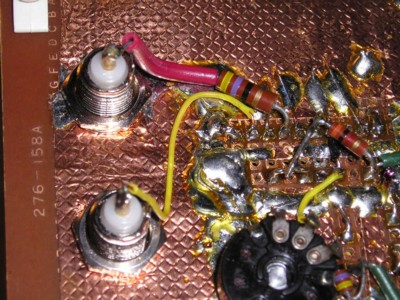
Figure 6. Underside of Oscillator
(note wire connections to output)
(note wire connections to output)
If the measurement to be made is inside of a metal equipment enclosure and the shield of the differential probe is securely connected 360 degrees to the metal enclosure as the cable passes through, rejection of EMI is much better that the result of Figure 5. It is not too difficult to get the EMI down to a few hundred millivolts or less for a similar source of EMI.
A lower frequency version of a passive differential probe useful to hundreds of MHz is described in my November 1994 article in the IEEE Circuits and Devices Magazine (~3.2 MB pdf file). A probe of this design as well as the higher frequency probe used in this article are available from Fischer Custom Communications.
Summary:
Whenever measurements are made in the face of severe EMI
such as ESD, a passive differential probe can be very useful
where active probes would saturate from the high common mode noise and
unbalanced probes don't work because of noise pickup.
I want to thank Deb (Didi) Smith, my daughter and a Sophomore in Electrical Engineering at the University of California at Santa Barbara, for help in performing the experiment for this Technical Tidbit.
I want to thank Deb (Didi) Smith, my daughter and a Sophomore in Electrical Engineering at the University of California at Santa Barbara, for help in performing the experiment for this Technical Tidbit.
Other articles on this website related to this topic are:
- November 1994 article in the IEEE Circuits and Devices Magazine (~3.2 MB pdf file)
- 50 MHz Oscillator
- July 1999: The Shorted Scope Probe Problem
- June 2000 supplement, Ground Lead, Friend or Foe?
- June 2001, A Static Field Powered EMI Source
- September 2001, Improving FET Probe Immunity to Unwanted Noise Pickup
- March 2003, Minimizing Errors in Oscilloscope Measurements
- November 2006, Measuring Signals in the Presence of Severe EMI - Part 1, How Not to Do It
- December 2006, Measuring Signals in the Presence of Severe EMI - Part 2, A Differential Solution
- Data sheet for passive differential probe used in this article (~450 kB pdf file) by Fischer Custom Communications
- KeyTek MiniZap ESD Simulator
- Agilent 54845a Infiniium Oscilloscope
Click here for a description of my latest seminar to be available soon titled:
EMC
Lab Techniques for Designers
(How to find EMC problems and have some confidence your system will pass EMC testing while it is still in your lab).
(How to find EMC problems and have some confidence your system will pass EMC testing while it is still in your lab).
 |
Check out my podcast containing mp3 format short tutorials, tech news and more! Just click on the microphone to see the listing
of free
audio programs. Content is added every week on technical topics so check back frequently. |
Home