
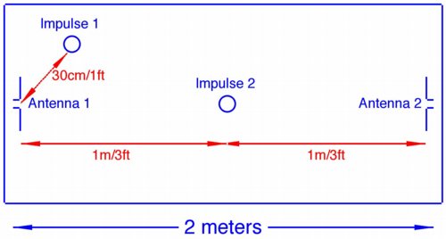
Figure 1. Two Dimensional Example Having Two Impulse Sources and Two Antennas
Abstract: ESD and other impulsive
events can be physically located by using time of arrival of the
generated EMI at multiple antennas as displayed on a fast
digitizing oscilloscope. In field conditions, the method described is
fast and accurate.
Discussion: ESD and similar impulse sources, such as electrical fast transients (EFT), can cause both soft errors and failures in electronic equipment and devices. In many cases, such as electronic device manufacturing, sources of ESD events involving the manufactured device must be found and eliminated. This is especially the case as many high performance and specialized devices are becoming more ESD sensitive. Just using ESD dissipative materials is not necessarily enough, especially in a clean room environment. In mission critical equipment such as medical, air traffic control, and server farms (510K pdf file), ESD events can disrupt operations and sources of these events should be identified and eliminated.
One method of locating ESD events in space is by using time of arrival at multiple antennas. This is like a time domain equivalent of triangulating on a radio transmission using multiple directional antennas. Locating an ESD event requires at least three antennas, but the job can often be done with two antennas and a little judgment if the event ESD is repeatable. One such case is illustrated in Figure 1, an example with two impulse sources and two antennas. It is important to connect the antennas to the oscilloscope with cables that have the same time delay and loss.
If the source is at impulse 2, the signal will arrive at both antennas at the same time, since they are the same distance away. Really, all we know is that the source is equidistant between the antennas. This condition is satisfied anywhere on a disk centered on the line between the two antennas and perpendicular to it. However, in a real lab situation enough information is known to narrow the range of possibilities. In a piece of equipment handling integrated circuit chips, the activity is often approximately on a plane, like Figure 1, and so the points equidistant from the antennas become a line perpendicular to and in the middle of a line connecting the two antennas and lying in the plane of the table. By observing the operation of the equipment, likely possibilities for ESD events (locations involving motion and contact) can be identified. Using judgement along with an initial antenna positions often quickly identifies the location of the ESD event for cases like this.
If one or both the antennas are moved and the event recreated, the location can be determined to accuracy of the sampling rate on the oscilloscope. Since electromagnetic waves in free space travel about one ft/ns, or ~30 cm/ns, a scope that samples at four GSa/sec can resolve distances of about 1/4 foot (~7.5 cm). This resolution is adequate for most uses where the dimensions of the area of interest are on the order of a few meters.
For instance, if antenna 1 is moved two feet closer to antenna 2, then its output due to impulse 2 will occur two nanoseconds earlier than the output of antenna 2 and the difference between the antennas will be two nanoseconds. Since the direction of antenna movement was towards antenna 2, one can conclude that impulse 2 must be on a line midway between the two original antenna positions. By moving the antennas and noting the results, the event can be located.
For an ESD event location at impulse 1, the scope will show that antenna 1 picked up the signal about four nanseconds earlier than antenna 2. This is because the delay to antenna 1 is about one nanosecond and the delay to antenna 2 is about five nanoseconds. By moving either of the antennas and noting the relative arrival times, the position can be calculated. If the event repeats relatively quickly, an antenna can be moved in real time and "home" in on the event location. The location will be the earliest arrival time at the antenna. In practice, one can often figure out where the event is without moving the antennas at all, just by inspection of the machine or area as the events occur as noted earlier in this article.
A third antenna would allow the position to be calculated without moving the antennas. Using a third antenna requires another oscilloscope channel, increasing the cost of the scope and possibly slowing its sampling rate as well. I often use two antennas and move them around to different positions to provide increased confidence in the calculation of the position of the ESD event or to "home" in on the event in real time.
A real life example of locating an ESD or fast impulse source in real time within an aisle of equipment would be as follows: set two antennas about two meters apart attached to a rolling card holding the scope, one antenna in front and the other behind the direction of movement of the cart. As the noise source is approached, but still relatively far away, the time of arrival at the lead antenna will be first compared the the following antenna by the distance between them. As the source is approached, the time of arrival at the two antennas will approach the same time and become equal as the event source is passed. After passing the event, the following antenna will see the event arrival first. The event location is closest to the rolling cart when the time of arrival is the same at both antennas. Under this condition, the event could be located to the left, right, above, or below the midpoint between the antennas.
Figure 2 shows a typical scope plot from two antennas located two meters apart. For measurements of this type, sin(x)/x interpolation on the scope should be turned off. The waveform of channel 3 (purple) clearly starts about five to six nanoseconds before the waveform on channel 1 (yellow). Since the antennas are about six feet (nanoseconds) apart, two meters, this means the event must be close to a line between the two antennas and extended beyond them, being closer to the antenna connected to channel 3. Note that the amplitude shown on channel 3 is stronger than channel 1. This also usually, but not always, means the signal source is closer to the antenna connected to channel 3.
The waveforms actually displayed on the scope are due as much, or more, to the impulse response of the antenna as to any characteristics of the source. But, for event location, we are usually only concerned with time of arrival of the wavefront. If one wanted to look more accurately at the radiated EMI waveform, a TEM antenna would have to be used. Even with simple dipoles or loops, the waves displayed on the scope can yield information about the ESD source such as peak current in the event, the voltage of the discharge, and the length of the arc. In some cases, interpretation of the relative amplitudes between the two channels can yield more information of the distance to the event. There are a number of complications that can arise, such as intervening objects and antenna size. A detailed discussion on these topics and more are included in the audio discussion of this article at http://emcesd-p.com.
Two computational algorithms for calculating the location of ESD events were described in two separate papers by J. Bernier and D. Lin at the 1997 EOS/ESD Symposium. The EOS/ESD Symposium is sponsored by the ESD Association.
Summary: By using multiple channels on an oscilloscope and simple antennas, the location in space of ESD and other fast impulses can be determined. For many cases, the process is relatively simple and useful.
Discussion: ESD and similar impulse sources, such as electrical fast transients (EFT), can cause both soft errors and failures in electronic equipment and devices. In many cases, such as electronic device manufacturing, sources of ESD events involving the manufactured device must be found and eliminated. This is especially the case as many high performance and specialized devices are becoming more ESD sensitive. Just using ESD dissipative materials is not necessarily enough, especially in a clean room environment. In mission critical equipment such as medical, air traffic control, and server farms (510K pdf file), ESD events can disrupt operations and sources of these events should be identified and eliminated.
One method of locating ESD events in space is by using time of arrival at multiple antennas. This is like a time domain equivalent of triangulating on a radio transmission using multiple directional antennas. Locating an ESD event requires at least three antennas, but the job can often be done with two antennas and a little judgment if the event ESD is repeatable. One such case is illustrated in Figure 1, an example with two impulse sources and two antennas. It is important to connect the antennas to the oscilloscope with cables that have the same time delay and loss.
If the source is at impulse 2, the signal will arrive at both antennas at the same time, since they are the same distance away. Really, all we know is that the source is equidistant between the antennas. This condition is satisfied anywhere on a disk centered on the line between the two antennas and perpendicular to it. However, in a real lab situation enough information is known to narrow the range of possibilities. In a piece of equipment handling integrated circuit chips, the activity is often approximately on a plane, like Figure 1, and so the points equidistant from the antennas become a line perpendicular to and in the middle of a line connecting the two antennas and lying in the plane of the table. By observing the operation of the equipment, likely possibilities for ESD events (locations involving motion and contact) can be identified. Using judgement along with an initial antenna positions often quickly identifies the location of the ESD event for cases like this.
If one or both the antennas are moved and the event recreated, the location can be determined to accuracy of the sampling rate on the oscilloscope. Since electromagnetic waves in free space travel about one ft/ns, or ~30 cm/ns, a scope that samples at four GSa/sec can resolve distances of about 1/4 foot (~7.5 cm). This resolution is adequate for most uses where the dimensions of the area of interest are on the order of a few meters.
For instance, if antenna 1 is moved two feet closer to antenna 2, then its output due to impulse 2 will occur two nanoseconds earlier than the output of antenna 2 and the difference between the antennas will be two nanoseconds. Since the direction of antenna movement was towards antenna 2, one can conclude that impulse 2 must be on a line midway between the two original antenna positions. By moving the antennas and noting the results, the event can be located.
For an ESD event location at impulse 1, the scope will show that antenna 1 picked up the signal about four nanseconds earlier than antenna 2. This is because the delay to antenna 1 is about one nanosecond and the delay to antenna 2 is about five nanoseconds. By moving either of the antennas and noting the relative arrival times, the position can be calculated. If the event repeats relatively quickly, an antenna can be moved in real time and "home" in on the event location. The location will be the earliest arrival time at the antenna. In practice, one can often figure out where the event is without moving the antennas at all, just by inspection of the machine or area as the events occur as noted earlier in this article.
A third antenna would allow the position to be calculated without moving the antennas. Using a third antenna requires another oscilloscope channel, increasing the cost of the scope and possibly slowing its sampling rate as well. I often use two antennas and move them around to different positions to provide increased confidence in the calculation of the position of the ESD event or to "home" in on the event in real time.
A real life example of locating an ESD or fast impulse source in real time within an aisle of equipment would be as follows: set two antennas about two meters apart attached to a rolling card holding the scope, one antenna in front and the other behind the direction of movement of the cart. As the noise source is approached, but still relatively far away, the time of arrival at the lead antenna will be first compared the the following antenna by the distance between them. As the source is approached, the time of arrival at the two antennas will approach the same time and become equal as the event source is passed. After passing the event, the following antenna will see the event arrival first. The event location is closest to the rolling cart when the time of arrival is the same at both antennas. Under this condition, the event could be located to the left, right, above, or below the midpoint between the antennas.
Figure 2 shows a typical scope plot from two antennas located two meters apart. For measurements of this type, sin(x)/x interpolation on the scope should be turned off. The waveform of channel 3 (purple) clearly starts about five to six nanoseconds before the waveform on channel 1 (yellow). Since the antennas are about six feet (nanoseconds) apart, two meters, this means the event must be close to a line between the two antennas and extended beyond them, being closer to the antenna connected to channel 3. Note that the amplitude shown on channel 3 is stronger than channel 1. This also usually, but not always, means the signal source is closer to the antenna connected to channel 3.
Figure 2. Typical Scope Plot of Two Antenna Setup
The waveforms actually displayed on the scope are due as much, or more, to the impulse response of the antenna as to any characteristics of the source. But, for event location, we are usually only concerned with time of arrival of the wavefront. If one wanted to look more accurately at the radiated EMI waveform, a TEM antenna would have to be used. Even with simple dipoles or loops, the waves displayed on the scope can yield information about the ESD source such as peak current in the event, the voltage of the discharge, and the length of the arc. In some cases, interpretation of the relative amplitudes between the two channels can yield more information of the distance to the event. There are a number of complications that can arise, such as intervening objects and antenna size. A detailed discussion on these topics and more are included in the audio discussion of this article at http://emcesd-p.com.
Two computational algorithms for calculating the location of ESD events were described in two separate papers by J. Bernier and D. Lin at the 1997 EOS/ESD Symposium. The EOS/ESD Symposium is sponsored by the ESD Association.
Summary: By using multiple channels on an oscilloscope and simple antennas, the location in space of ESD and other fast impulses can be determined. For many cases, the process is relatively simple and useful.
Other articles on this website related to this topic are:
- January 2000: Displaying Measurement Error
- April 2000, Paper Clips and the Speed of Light
- December 2001, The Elusive Glitch - Part 3, Measurement of Impulsive Fields
- August 2003, Sin(x)/x, The Forgotten Setting - Part One
- September 2003, Sin(x)/x, The Forgotten Setting - Part Two, An EMI Example
- The EMI/ESD Environment of Large Server Installations (510K pdf file)
Additional Material: An in-depth audio-visual format tutorial on this subject, covering background as well as more technical details, is available at: http://emcesd-p.com.
If you like the information in this article and others on this website, much more information is available in my courses. Click here to see a listing of upcoming courses on design, measurement, and troubleshooting of chips, circuits, and systems.