High Frequency MeasurementsWeb Page
Douglas C. Smith

 Address:  P. O. Box 1457, Los Gatos,CA 95031
 TEL:     800-323-3956/408-356-4186
 FAX:     408-358-3799
 Mobile:   408-858-4528
 URL:     www.dsmith.org
 Email:    doug@dsmith.org


Technical Tidbit - December 2003
Troubleshooting Noise From Pulse Width Modulation Controlled 3 Phase Motors and Controls

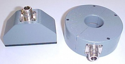
 F40 and F90 probes
Figure 1. Probes Useful for Tracking PWM Motor Currents
(F-90 probe, left, and F-40 probe, right)

Abstract:  Pulse width modulation controlled 3 phase motors have becomepopular in numerous applications from small fractional hp motors to giantindustrial motors. Common mode currents generated by the controller circuitsand motors can cause signal interference to other circuits at relativelylow frequencies. At these low switching frequencies used, some shieldingand circuit design techniques do not work well. The result can be interferenceto low level higher frequency circuits. Troubleshooting techniques are presented.
Discussion: Pulse width modulation, PWM, controlled motors often use switchingfrequencies on the order of 10 kHz, much lower than what is normally considered"high frequency." However, the fundamental switching frequency and its harmonicscan interfere with the operation of associated higher frequency circuits.

Common mode currents from the PWM controlled power fed to the motor windings can couplethrough the capacitance from the windings to the motor frame and resultin significant currents that flow in the metal structures of the machine. Thesecurrents can cause enough voltage drop in "ground" to affect other circuits.In one case, such ground drops caused the common mode voltage on the balancedinput to a high frequency device to exceed the device specifications. The result caused the circuit to malfunction.

The key to this problem is to either reduce the common mode currentsor lower the ground impedance, which includes a significant resistive component at these low frequencies. One way to reduce common mode currents on the motor cables is to shield them. Normally, at high frequencies, the common mode currenton the motor cables would be matched by a current in the opposite directionon the shield (if both ends of the shield are connected with low impedanceconnections) so the net common mode current on the cable would be significantlyreduced as would currents in the machine's metal structure. However, at frequenciesof a few kHz, shield resistance becomes an important effect that limits theshield effectiveness as it becomes comparable to the shield inductance. Anotherway of thinking about the effect is that the skin depth of the shield becomescomparable to its actual thickness. Click herefor a skin depth calculator. Its accuracy is in question at the low frequenciesconsidered here but it can give a general idea of skin depths at variousfrequencies.

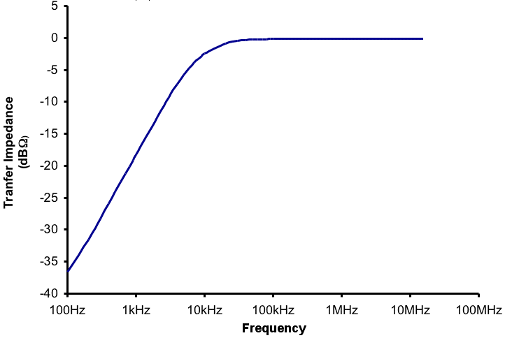
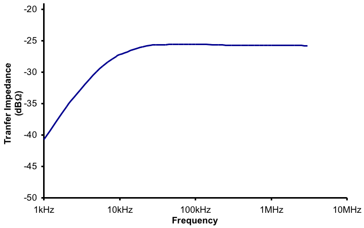
How can these common mode cable and ground currents be measured andtheir paths traced? Figure 1 shows a pair of current probes from FischerCustom Communications, an F-40 current probe and an F-90 surface currentprobe. Figures 2 and 3 below show the frequency response of these probes.They both have low frequency response to several kHz and enough high frequencyresponse to cover many harmonics of the switching frequencies of PWM controlledmotor circuits.  In addition, at frequencies above a few MHz, a gooddouble braid shield can work well enough to significantly reduce ground currents,making them less of a problem. So these two probes cover the frequency rangeof interest for PWM controlled motors. Both probes can handle hundreds ofAmperes or more of power current so that probe core saturation is generallynot a problem, especially since common mode currents on the motor cablesare of interest here (zero net power current).

  F40 response curve
Figure 2. F-40 Response

F90 response
Figure 3. F-90 Response

Tracing PWM currents in cables and the ground structure requires a pairof matched F-40 current probes (or similar) and an F-90 surface current probe(or similar). First, an F-40 is placed around the motor power cables (all conductors including a shield, if present) to measure the common mode current on the cables. Fischer Custom Communications indicates that special probescan be designed for large cables. A digital scope capable of displaying thefundamental and harmonics to several tens of MHz should be used. An analogscope will work, but is limited as to display and storage options. The currentflowing in common mode on the power cables (including a shield, if present)is just the current that is flowing back in the machine structure.

One troubleshooting method would be to trigger the oscilloscope on the common mode motor current. Then, using thesecond F-40 and the F-90 probes, currents can be traced throughout the system.By triggering on the motor common mode current, the other probes can tellthe direction of current flow as well as magnitude. For instance, an F-40placed around another system cable can tell if some of the motor currentsare present or an F-90 can find where in the metal structure that motor currentsare flowing.  While triggering on the common mode current, a suitablevoltage probe can be used to measure noise voltages in sensitive circuitsthat are due to the motor currents, such as the common mode voltage at a balancedinput.

The key is to trigger the scope from the common mode currents on the motorpower cable (all leads carrying power to the motor, including a shield if present).The technique is similar to that described in the paper on thissite, A Method for TroubleshootingNoise Internal to an IC (~140K),where a scope is triggered from a loop positioned above a chip and a voltageprobe is used to find where the noise picked up by the loop shows up on thechip outputs, although much higher frequencies are present in that case.

A word of caution: Be careful if you want toclamp a current probe around just one (really, less than all) of the motorpower leads. The current probes described here can withstand a lot of power current(hundreds of Amperes or more) without saturating. However, the probes will be heldclosed with great force (you do not want your fingers in the way) by themagnetic field from the power current. The probes will not be able to be removedfrom the cable without turning off the power. Never clamp a current probearound a power conductor carrying many Amperes of current where you cannot break the power circuit. If you do,the current probe may be on the cable for a long, long time!

Summary and Conclusion: Low frequency common mode currents on PWMcontrolled motors can cause problems in other associated circuits. Frequencieson the order of tens of kHz (fundamental and harmonics) cause shields tobe less effective, due to shield resistance, in reducing common mode PWMcurrents on motor power cables. Given a stable trigger from the common modemotor currrents, current probes can be used to trace these currents throughthe system and voltage probes can measure the resultant voltages in circuitsdue to the motor currents.


Interesting websites with information relating to this article and PWM controlled motors are:

Other articles on this website covering current probes include:

Top of page
Home


Questions or suggestions? Contact me at doug@dsmith.org
Copyright © 2003 Douglas C. Smith