
Address: P. O. Box 1457, Los Gatos,
CA 95031
TEL:
800-323-3956/408-356-4186
FAX:
408-358-3799
Mobile: 408-858-4528
URL:
www.dsmith.org
Email: doug@dsmith.org
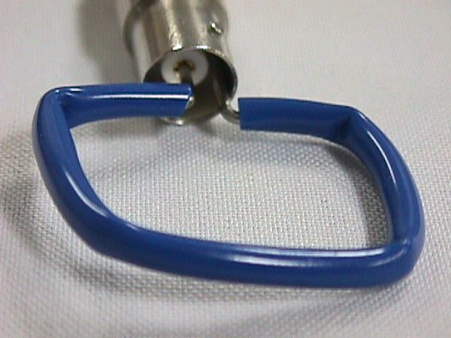
In the picture above, a paper clip (any stiff wire will do) is bent into a square shape and covered with insulation, forming an unshielded magnetic loop probe. Such a structure can be quite useful in circuit troubleshooting and noise investigations. A conductor carrying a current, i, will have a voltage drop across it given by:
e1 = Ldi/dt + Ri
e1 = Ldi/dt
A conductor nearby the current carrying conductor, such as a side of the square loop above, will pickup an open circuit voltage of:
e2 = Mdi/dt
Using this principle, a simple square loop, such as the one above, can be used to estimate the voltage drop across conductors. When the probe is held up to a conductor carrying high frequency current, the probe's open circuit output voltage is a lower bound for the voltage between the corners of the probe along the current carrying conductor.
The probe should be connected to a oscilloscope or spectrum analyzer using a coaxial cable terminated in its characteristic impedance. This resistive load on the loop in combination with the self inductance of the loop form a low pass filter on the probe output. For a loop with sides of 1 cm, this corner frequency will be between 200 and 300 MHz.
Possible uses are estimating the drop across bonding
wires and lead frames of integrated circuits or measuring noise effects
on a printed wiring board. My paper in the 1999
IEEE EMC Symposium Proceedings discusses such uses of magnetic loops
in more detail as well as the theory and limitations of such probes.