
Address: P. O. Box 1457, Los Gatos,
CA 95031
TEL:
800-323-3956/408-356-4186
FAX:
408-358-3799
Mobile: 408-858-4528
URL:
www.dsmith.org
Email: doug@dsmith.org
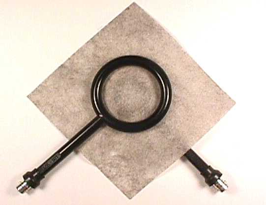
In the picture above, two shielded magnetic loops are placed on opposite sides of a sample of shielding material. One loop is driven by a signal source and the other loop is connected to a measuring instrument such as an oscilloscope or spectrum analyzer. The magnetic flux that penetrates the shielding material and passes through the second loop generates a signal in that loop. The output of the second loop gives a measure of the shielding effectiveness of the material to an incident magnetic field perpendicular to the shielding material.
Normally, shielding effectiveness of a material is measured using plane waves in the far field (relatively far from the radiating antenna). In this case, the magnetic field of the wave is parallel to the shielding material. Measurements made this way are often too expensive or difficult to do in a development lab. And, if one is shielding one compartment of a small product, such as a cell phone, from another compartment, the shielding material is not far enough from the radiating circuit for the plane wave assumption to be valid. Usually in this case, the shield material is illuminated with a magnetic field from currents flowing in the nearby circuitry. Under these conditions, the measurement pictured above is a far more accurate indicator of the real shielding effectiveness of the material.
Figure 1 below shows two loops positioned close to each other. The loops should be shielded magnetic field probes, such as ETS-Lindgren model 7405 (~562K pdf file) or equivalent. They should be positioned just far enough apart for the proposed shielding material to be inserted during the second part of the measurement.
Loop 1 is excited from a source and generates a magnetic field. A few possible magnetic field lines are shown in Figure 1. The magnetic flux that passes through the second loop generates a voltage as per Faraday's Law. Usually the frequency of the source is swept and the output plotted with respect to frequency. This is easy to do using a spectrum analyzer with a tracking generator. Loop 1 is connected to the output of the tracking generator and loop 2 is connected to the spectrum analyzer input.
Figure 1. Transmission Between Two Loops
A sample of the shielding material is then placed between the two loops. It is important to maintain the initial loop spacing during this step. The magnetic flux trying to penetrate the shielding material causes eddy currents to flow in the shielding material. These currents cancel part of the magnetic field so that a reduced field passes through the second loop compared to the field passing through the second loop when the shielding material is not present. The output of the second loop is plotted with respect to frequency and the result shows how well the shielding material works over the frequency range of interest. Smaller loops work to higher frequencies and also can resolve differences of shielding effectiveness over smaller distances. The results of this test are often surprising.
Figure 2. Measuring Magnetic Field Attenuation
Through Shielding Material
Shielding material that is rated in the 60 to 100 dB range for plane wave illumination often has much lower shielding effectiveness in many other applications (as well as this test), sometimes only in the range of 10 to 20 dB. If the material is being used within a product, especially a small one, specifying plane wave shielding effectiveness may not be a good choice. Measuring the magnetic field shielding effectiveness, as shown above, will likely be more closely related to the actual performance of the shield within the product. In the case of shielding materials, knowing the application and how it relates to specifications is extremely important if circuit performance is to be achieved.
For more information on magnetic loops in general and shielded magnetic loops in particular, see Signal and Noise Measurement Techniques Using Magnetic Field Probes, delivered at the 1999 IEEE EMC Symposium and available on this website.