
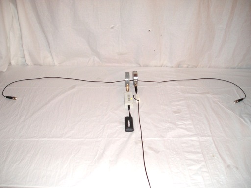
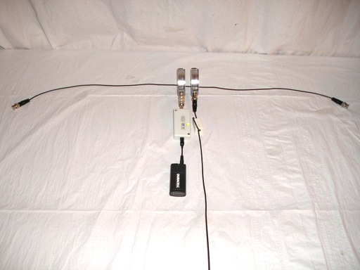
Figure 1. Test Setup with USB Powered Comb Generator, Current Probes, and 1.5 Meter Cable
Abstract: A comb generator RF source can be a handy substitute when a
tracking generator is not available on a spectrum analyzer.
In
this case, a USB powered comb generator RF source is used to
supply the signal used to measure the resonant frequencies of a
cable.
Discussion: Figure 1
shows an AET USB-S-1.84 RF Source comb generator and two matched Fischer F-33-1
current probes being used to measure the resonant frequencies of a 1.5
meter cable. The comb generator feeds one current probe, inductively
generating a series voltage on the cable using the current probe as a
transformer. A second current probe is
used to sense the resulting current in the cable.
A close-up of the comb generator and current probes is shown in Figure 2. There is a ferrite core on the cable of the sensing current probe to help minimize the effective of capacitive coupling between the body of the probe and the cable being measured. Since the comb generator assembly is physically small for the frequencies used in this experiment, compared to the cable connecting the sensing probe to the spectrum analyzer, a ferrite core is of less importance on the "injection" probe.
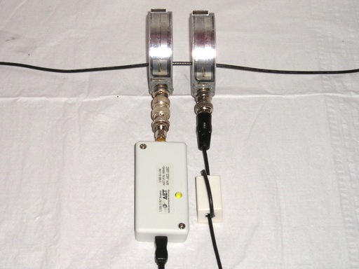
Figure 2. Close-up of Comb Generator, "Injection" Current Probe, and Sensing Current Probe
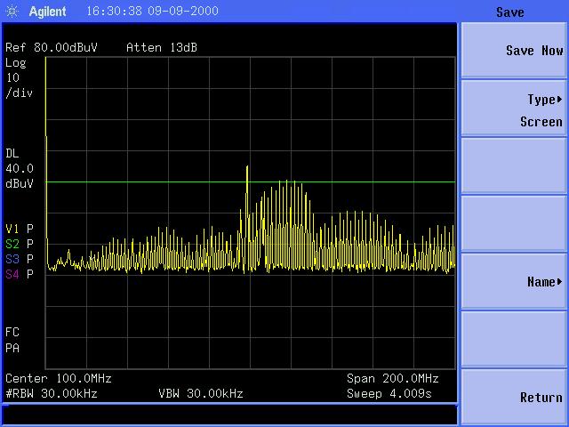
Figure 3 shows the spectra of the induced current in the 1.5 meter cable from zero to 200 MHz. The single peak in the center of the screen just below 100 MHz is due to a local FM broadcast station. A broad current peak can be seen around 80 MHz indicating cable resonance when driven from the position of the pair of current probes. If the probes are moved to a different position, resonant frequencies will also change as the cable becomes an asymmetric dipole.
Normally, the response around a cable resonance would be a smooth rise to a maximum whose width is determined by the Q of the resonance, but Figure 3 shows a wavy effect. This is due to the frequency spectra of the comb generator itself which is shown in Figure 4. If the plot in Figure 4 could be normalized to a constant amplitude for all the harmonics and this normalization was then applied to the data in Figure 3, the wavy pattern of amplitude with frequency in Figure 3 would disappear. However, even without this normalization, it is clear the cable has a primary resonance around 80 MHz.
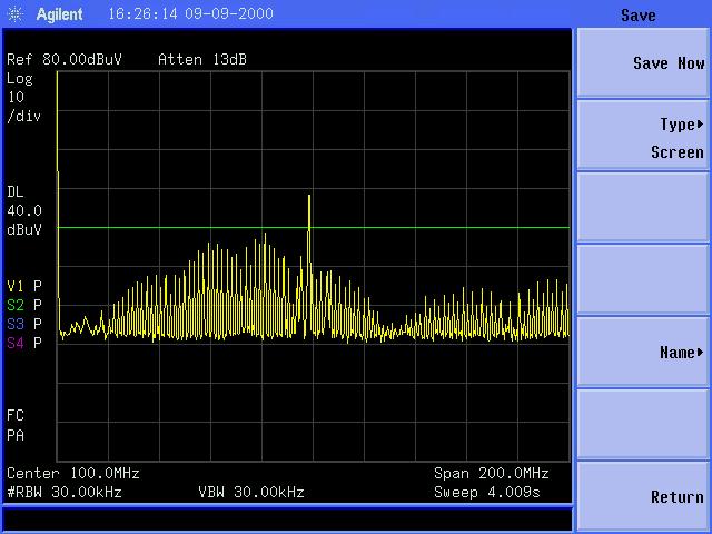
Figure 3. Frequency Spectra of Sensed Current For 1.5 Meter Cable
(Vertical Scale = 10 dB/div, Horizontal Scale = 20 MHz/div)
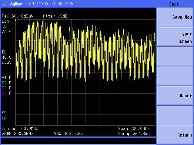
Figure 4. Frequency Spectra of Comb Generator Output
(Vertical Scale = 10 dB/div, Horizontal Scale = 20 MHz/div)
Results for the same measurement, except that a 1 meter cable is used, is shown in Figure 5 and the spectra of the resulting cable current is shown in Figure 6. The resonance has moved up to about 120-130 MHz, commensurate with the shorter length of the one meter cable.
A close-up of the comb generator and current probes is shown in Figure 2. There is a ferrite core on the cable of the sensing current probe to help minimize the effective of capacitive coupling between the body of the probe and the cable being measured. Since the comb generator assembly is physically small for the frequencies used in this experiment, compared to the cable connecting the sensing probe to the spectrum analyzer, a ferrite core is of less importance on the "injection" probe.
Figure 2. Close-up of Comb Generator, "Injection" Current Probe, and Sensing Current Probe
Figure 3 shows the spectra of the induced current in the 1.5 meter cable from zero to 200 MHz. The single peak in the center of the screen just below 100 MHz is due to a local FM broadcast station. A broad current peak can be seen around 80 MHz indicating cable resonance when driven from the position of the pair of current probes. If the probes are moved to a different position, resonant frequencies will also change as the cable becomes an asymmetric dipole.
Normally, the response around a cable resonance would be a smooth rise to a maximum whose width is determined by the Q of the resonance, but Figure 3 shows a wavy effect. This is due to the frequency spectra of the comb generator itself which is shown in Figure 4. If the plot in Figure 4 could be normalized to a constant amplitude for all the harmonics and this normalization was then applied to the data in Figure 3, the wavy pattern of amplitude with frequency in Figure 3 would disappear. However, even without this normalization, it is clear the cable has a primary resonance around 80 MHz.
Figure 3. Frequency Spectra of Sensed Current For 1.5 Meter Cable
(Vertical Scale = 10 dB/div, Horizontal Scale = 20 MHz/div)
Figure 4. Frequency Spectra of Comb Generator Output
(Vertical Scale = 10 dB/div, Horizontal Scale = 20 MHz/div)
Results for the same measurement, except that a 1 meter cable is used, is shown in Figure 5 and the spectra of the resulting cable current is shown in Figure 6. The resonance has moved up to about 120-130 MHz, commensurate with the shorter length of the one meter cable.
Figure 5. Test Setup with USB Powered Comb Generator, Current Probes, and One Meter Cable
Figure 6. Frequency Spectra of Sensed Current For One Meter Cable
(Vertical Scale = 10 dB/div, Horizontal Scale = 20 MHz/div)
(Vertical Scale = 10 dB/div, Horizontal Scale = 20 MHz/div)
Summary:
An inexpensive comb generator RF source can be used instead of an expensive
tracking generator for some EMC measurements. In this case, it was shown that a comb
generator can be used with two current probes to measure cable
resonances.
Additional articles on this website related to this topic are:
- March 2006, Predicting Cable Emissions from Common Mode Current
- January 2008, Using Current Probes to Measure Cable Resonance
(Current Probes, More Useful Than You Think - Part 3) - August 2009, The Square Shielded Loop - Part 6, Measurements in the Time Domain Using a Comb Generator
(An unusual use for a comb generator) - September 2009, Using a Two AA Cell USB Charger to Power a Comb Generator
(A Handy Power Soure for Any USB Powered Device) - October 2009, Using a Comb Generator to Demonstrate Impairment of the Shielding Effectiveness of a Coaxial Cable
(A Useful Demonstration Technique When a Tracking Generator is not Available)
- USB powered Comb Generator
- Agilent N9320B Spectrum Analyzer
- Fischer Custom Communications F-33-1 Current Probe
If you like the information in this article and others on this website, much more information is available in my courses. Click here to see a listing of upcoming courses on design, measurement, and troubleshooting of chips, circuits, and systems. Click here to see upcoming seminars in Newport Beach, CA.
Click here for a description of my latest seminar titled (now also available online as a WebEx seminar).
EMC
Lab Techniques for Designers
(How to find EMC problems and have some confidence your system will pass EMC testing while it is still in your lab).
(How to find EMC problems and have some confidence your system will pass EMC testing while it is still in your lab).
 |
My new website for engineers and technicians, CircuitAdvisor.com, is coming! The site will contain technews and analysis programs, cartoons, multimedia tutorials and more.The site will be open soon. |
Home