
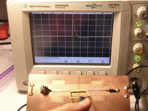
Figure 1. Measuring the Coupled Signal into a Circuit Path From a Square Unshielded Wire Loop in the Time Domain
Abstract: Shielded loops are
often used to minimize electric field (capacitive) coupling. A case is
shown where using both unshielded and shielded magnetic loops to inject
signals into a path on a circuit board
results in an injected signal that is about the same for both loops.
Unshielded wire loops are thus shown to be as useful as shielded loops for pulse injection.
Discussion: Figure 1 shows a
square unshielded wire loop held next to a path crossing a break in the
ground plane of a test board that is used for many experiment on this
website. The injected signal from a Fischer Custom Communications TG-EFT pulse generator connected to the loop was measured at the BNC connector on the
board (left side) using an oscilloscope for cases where the loop is positioned as shown and for a 180 degree
rotation of the loop. A similar test was done using a square shielded loop as shown in Figure 2. The construction of the
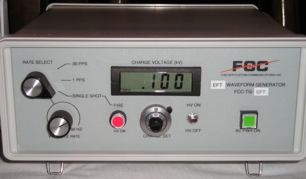
shielded loop is shown in the May 2008 Technical Tidbit, The Square Shielded Loop - Part 1. Bandwidth of the oscilloscope used was 500 MHz and the TG-EFT was
set to generate open circuit pulses of 100 Volts with a risetime of
about 2 ns and a pulse duration of about 100 ns. Figure 3 shows the
TG-EFT pulse generator.
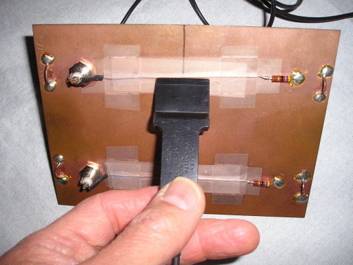
Figure 2. Coupling a Signal into a Circuit Path Using a Square Shielded Loop
(embedded in a plastic housing for strength)
Figures 4 and 5 show the results as displayed on the oscilloscope using the unshielded loop oriented in the both positions parallel to the path over the break in the ground plane, 180 degrees rotated from each other. Both plots have about the same pulse shape, amplitude, and width. Any change between the plots might be attributable capacitive coupling, however the only difference of any note is that the risetime in Figure 1 is a little faster than in Figure 2. The overall difference in the plots is not significant enough to make much difference when using pulse injection for troubleshooting designs.
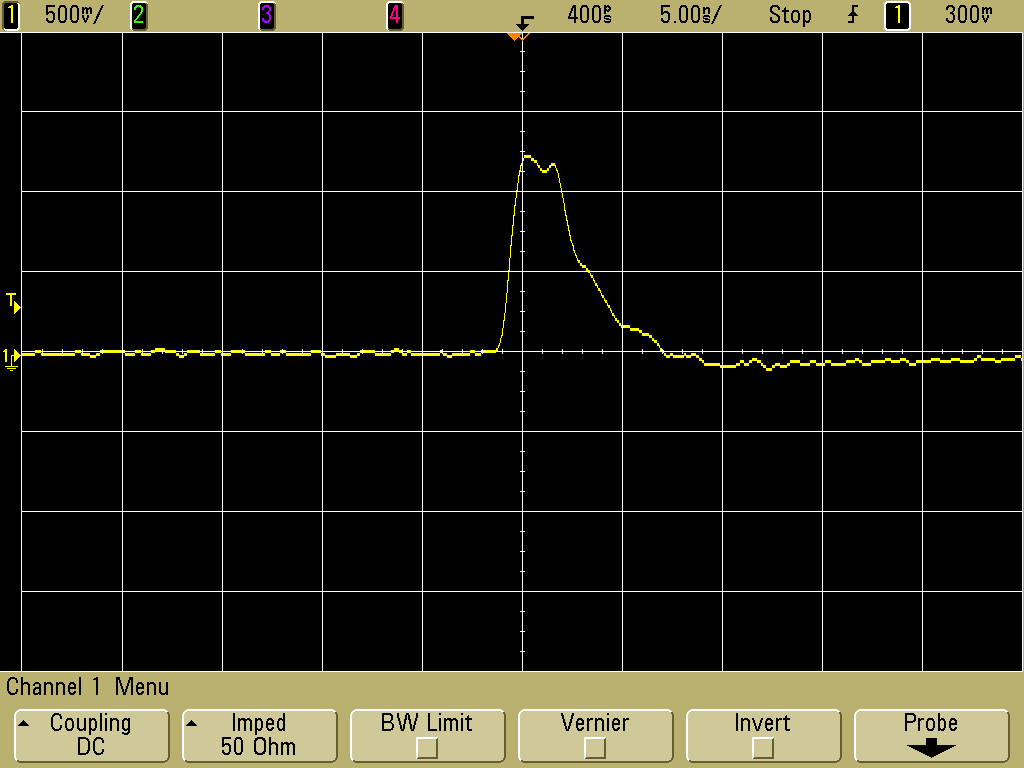
Figure 4. Injected Signal for Unshielded Loop
(Vertical scale = 500 mV/div, Horizontal scale = 5 ns/div)
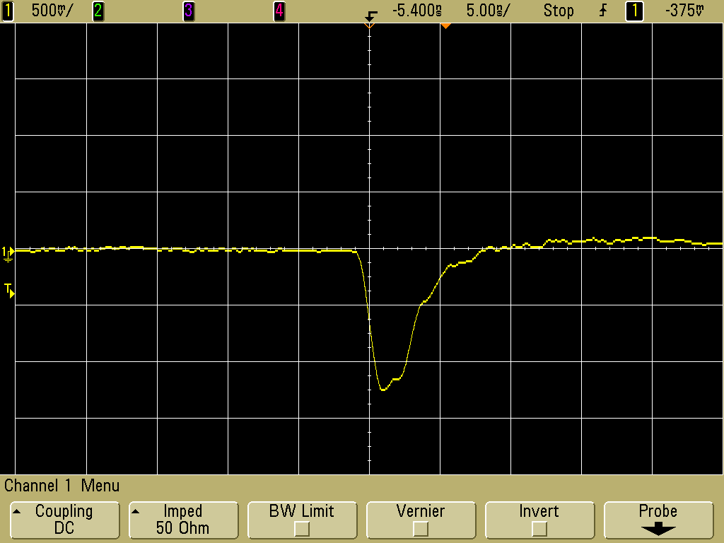
Figure 5. Injected Signal for Reversed Unshielded Loop
(Vertical scale = 500 mV/div, Horizontal scale = 5 ns/div)
The plots in Figures 6 and 7 for the shielded square loop are also very similar as well as having about the same risetime for both plots. The amplitude of the injected pulse is about 20% less because the distance between the center conductor of the semi-rigid coax forming the loop is further from the path on the circuit board due to the diameter of the coax and the thickness of the plastic housing. The slight improvement in matching of risetimes is not significant enough to warrant the extra complication and cost of shielded loops. In addition, if the scope had greater bandwidth, the resonance at about 600 MHz between the shielded loop and the board demonstrated in the August 2008 Technical Tidbit, The Square Shielded Loop - Part 4, Coupling to a PCB would likely cause distortions in the pulses displayed in Figures 6 and 7.
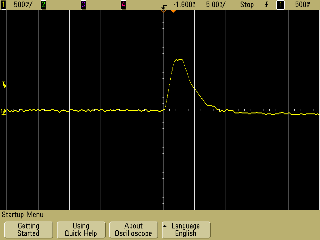
Figure 6. Injected Signal for Shielded Loop
(Vertical scale = 500 mV/div, Horizontal scale = 5 ns/div)
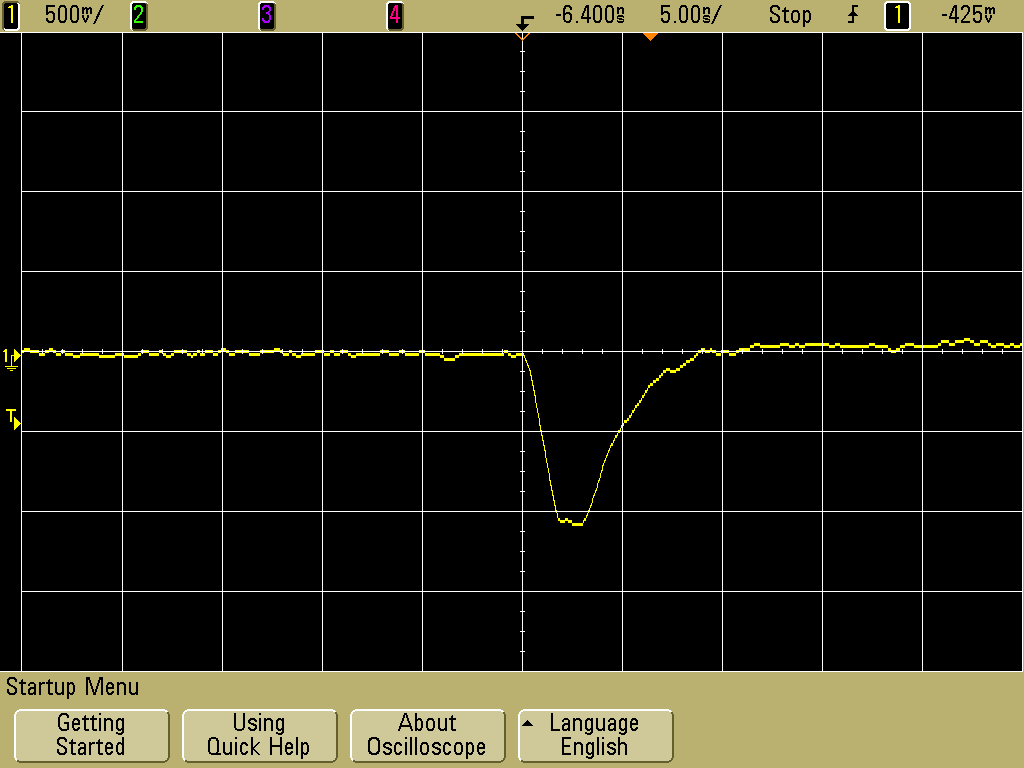
Figure 7. Injected Signal for Reversed Shielded Loop
(Vertical scale = 500 mV/div, Horizontal scale = 5 ns/div)
Figure 2. Coupling a Signal into a Circuit Path Using a Square Shielded Loop
(embedded in a plastic housing for strength)
Figure 3. Fischer Custom Communications TG-EFT Pulse Generator
Figures 4 and 5 show the results as displayed on the oscilloscope using the unshielded loop oriented in the both positions parallel to the path over the break in the ground plane, 180 degrees rotated from each other. Both plots have about the same pulse shape, amplitude, and width. Any change between the plots might be attributable capacitive coupling, however the only difference of any note is that the risetime in Figure 1 is a little faster than in Figure 2. The overall difference in the plots is not significant enough to make much difference when using pulse injection for troubleshooting designs.
Figure 4. Injected Signal for Unshielded Loop
(Vertical scale = 500 mV/div, Horizontal scale = 5 ns/div)
Figure 5. Injected Signal for Reversed Unshielded Loop
(Vertical scale = 500 mV/div, Horizontal scale = 5 ns/div)
The plots in Figures 6 and 7 for the shielded square loop are also very similar as well as having about the same risetime for both plots. The amplitude of the injected pulse is about 20% less because the distance between the center conductor of the semi-rigid coax forming the loop is further from the path on the circuit board due to the diameter of the coax and the thickness of the plastic housing. The slight improvement in matching of risetimes is not significant enough to warrant the extra complication and cost of shielded loops. In addition, if the scope had greater bandwidth, the resonance at about 600 MHz between the shielded loop and the board demonstrated in the August 2008 Technical Tidbit, The Square Shielded Loop - Part 4, Coupling to a PCB would likely cause distortions in the pulses displayed in Figures 6 and 7.
Figure 6. Injected Signal for Shielded Loop
(Vertical scale = 500 mV/div, Horizontal scale = 5 ns/div)
Figure 7. Injected Signal for Reversed Shielded Loop
(Vertical scale = 500 mV/div, Horizontal scale = 5 ns/div)
Summary:Capacitive
coupling from an unshielded loop is not always a problem
that requires the use of shielded loops to solve. On the
contrary, unshielded loops often work as well as shielded loops as
was
demonstrated by pulse injection in this Technical Tidbit. This series
of five
Technical Tidbits on square shielded loops has shown that unshielded
loops are useful in many cases and for injecting signals
into circuit
boards specifically. Unshielded loops can even outperform shielded
loops in some applications. Given the ease of constructing an
unshielded loop
and its low cost, this is an important result.
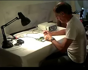
To see a short ~three minute video in mp4 format of using pulse injection to troubleshoot a circuit, click on the picture below. The picture links to the mp4 file on my podcast site http://emcesd-podcast.com. You can get the free VLC media player at http://www.videolan.org if your media player cannot play mp4 files. The free player Quicktime from Apple can also play mp4 files. Clicking on the picture should play the video in your browser or you can right click and select to save the linked content as a file on your computer.
To see a short ~three minute video in mp4 format of using pulse injection to troubleshoot a circuit, click on the picture below. The picture links to the mp4 file on my podcast site http://emcesd-podcast.com. You can get the free VLC media player at http://www.videolan.org if your media player cannot play mp4 files. The free player Quicktime from Apple can also play mp4 files. Clicking on the picture should play the video in your browser or you can right click and select to save the linked content as a file on your computer.
Additional articles on this website related to this topic are:
- Signal and Noise Measurement Techniques Using Magnetic Field Probes (~600K)
- (1999 IEEE EMC Symposium paper)
- December 2000, An Easy to Build Shielded Magnetic Loop Probe
- June 2006, Measuring Structural Resonances
- October 2007, Using Noise Injection for Troubleshooting Circuits
- November 2007, Measuring Structural Resonances in the Time Domain - Part 1
- February 2008, Using Resonant Frequency Measurements to Extract Circuit Parameters
(Calculating the Capacitance of a BNC Barrel Adapter) - May 2008, The Square Shielded Loop - Part 1
(Construction Details) - June 2008, The Square Shielded Loop - Part 2, Parasitic Coupling
- July 2008, The Square Shielded Loop - Part 3, Parasitic Coupling Between Unshielded Wire Loops
- August 2008, The Square Shielded Loop - Part 4, Coupling to a PCB
(From Shielded and Unshielded Magnetic Loops)
Equipment used in this Technical Tidbit:
- The oscilloscope used in this Technical Tidbit is an Agilent DSO5054A, a great little scope that is easy to use and boots in 9 seconds flat!
Click here for a description of my latest seminar titled (now available online as a WebEx seminar):
EMC
Lab Techniques for Designers
(How to find EMC problems and have some confidence your system will pass EMC testing while it is still in your lab).
(How to find EMC problems and have some confidence your system will pass EMC testing while it is still in your lab).
 |
Check
out my podcast containing mp3 format short tutorials, tech news and
more! Just click on the
microphone to see the listing
of free
audio programs. Content is added every week on technical
topics so check back frequently. |
Home