 High Frequency MeasurementsWeb Page
Douglas C. Smith Address: P. O. Box 1457, Los Gatos,CA 95031
TEL: 800-323-3956/408-356-4186
FAX: 408-358-3799
Mobile: 408-858-4528
URL: www.dsmith.org
Email: doug@dsmith.org
Technical Tidbit - February 2004
Measuring Printed Circuit Board Characteristic Impedance without a TDR(when you need a close answer fast!)
Abstract: In a crunch, being able to adapt test equipment to get a close answer fast can be a life saver.The characteristic impedance of a prototype circuit board was suspected as the cause of a 64 bit DDR SDRAM bus failing initialization tests and a method to confirm the board design was needed urgently. This Technical Tidbit describes the method by which a network analyzer was pressed into service and its useoutlined. This technique has been successfully used for analyzing other assemblies such as EIDE cables and USB unshielded twisted pairs.
Discussion: The relationship between inductance and capacitance for any transmission line is defined as (L/C)1/2. What was needed then was a way to measure the electrical components of the board fabrication and estimate the characteristic impedance by using the transmission line formula. Typically when boards that have impedance sensitive designs are manufactured, coupons are provided with test data that describes the board electrical details. Test coupons are small PCBs with exactly the same layer and trace construction as the main PCB. For example, a coupon will include traces of the same line width and copper weight on the same layer as the controlled impedances on the main PCB thereby providing an easy way to confirm the board design. The coupon is manufactured in the same process as the main board and with the same aperture code as used for the critical traces. An example of a coupon is shown is Figure 1.
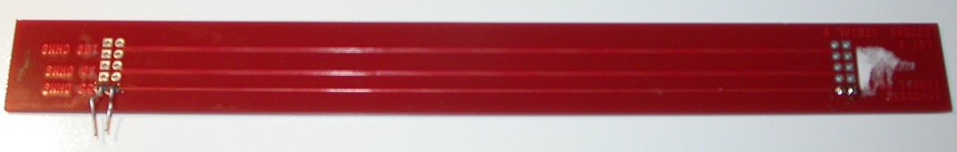 Figure 1.
 Printed Circuit Board Coupon
Test Method. The test coupon is a very simple pwb construction with traces that reflect the board stack-up and trace construction design. Test coupons will also have, typically, a set of vias connected to ground and the signal, in close proximity at one end of the trace, to allow a test probe to be attached. The test coupon shown inFigure 1 was ideal for testing in the impedance analyzer as not onlyare the test points are close to each other but there is a set at eachend of the trace making the modification for the inductance measurementvery simple indeed. The coupon is prepared by attaching wires to one endof the set of test points as shown in Figure 2 and the wires are usedto attach the coupon to the analyzer adapter as shown in Figure 3. Two measurementsare now taken with the test coupon in two different configurations: withthe second set of vias open (used in the capacitance measurements) andshorted ( used for the inductance measurement) as shown in Figures 4.After getting the capacitance and inductance numbers, use the transmissionline formula to estimate the characteristic impedance of the trace.
| 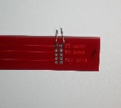 Figure 2. Coupon with wires attached.
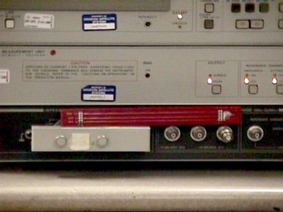
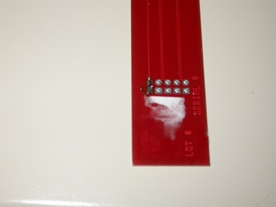
[note the desired impedance!] | 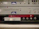 Figure 3. Coupon under test | 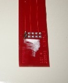 Figure 4. Coupon showing shorted signal. |
| (click on pictures for a larger image) |
From the plots: L = 37.5954 nH and C = 39.1054 pF
Zo (estimated) = 31 Ohms
Zo (measured) = 29 Ohms
Conclusion: When you need a close answer fast, a network analyzer can be pressed into service in place of a TDR. Typically the error for measuring the characteristic impedance of a circuit board is about 5% which can really add up so if you need a more accurate measurement then a TDR is the best instrument to use.
Editor's note: Be sure to select a test frequency high enough to easilymeasure the L and C values, but low enough to avoid standing waves on thecoupon's signal traces. For this article, Charles picked 3 MHz, a suitable frequency forthis case. If you are working with circuit boards 2 cm in length, a higherfrequency would be in order and control of the connection parasitics becomesmore important. Thanks goes to Charles for contributing this article.
Top of page
Home
Questions or suggestions? Contact me at doug@dsmith.orgCopyright © 2004 Douglas C. Smith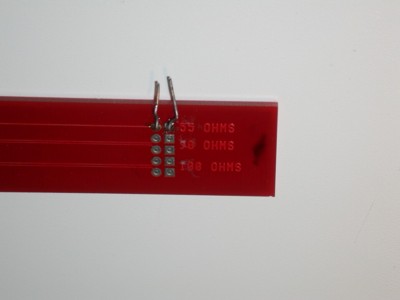