Cable Effects Part 1: Cable Discharge Events
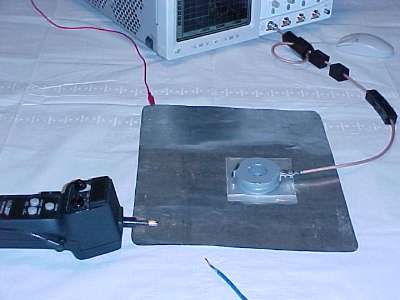
Figure 1. Test Setup

Address: P. O. Box 1457, Los Gatos,
CA 95031
TEL:
800-323-3956/408-356-4186
FAX:
408-358-3799
Mobile: 408-858-4528
URL:
www.dsmith.org
Email: doug@dsmith.org
Figure 1. Test Setup
Cable discharge events have been making the news lately. Reports of damage to Ethernet interfaces have occurred. A cable discharge event is an ESD (electrostatic discharge) event that happens when a cable acquires a static charge and then is connected to a piece of electronic equipment. The cable is often charged by pulling it across a floor surface when being installed. A cable can also have a charge induced on it if held in the hand of a person who has a static charge. In these cases, the cable charge exists on all of the conductors in common mode. The conductors can also be charged differentially by a couple of mechanisms, but that is not the subject of this article.
In the field, cables can become charged to different voltages over different parts of the insulating jacket, making for a complicated discharge event. To simplify the situation and to make comparisons between two different cable lengths, the conductors of a CAT 5 UTP (category 5 unshielded twisted pair) data cable were connected together and charged to 300 volts using an ESD simulator as a DC voltage source. This is the type of cable used for 10/100 Base T and other LAN networks. Figure 1 shows the test setup. A metal plane simulates a circuit board. The plane is connected to the scope chassis through the red wire to simulate a real ground connection and to prevent the plane from becoming charged itself. Ferrites on the scope cable help isolate the scope connection to the current probe from the measured discharge current. Without the ferrites, the discharge current can more easily couple through the parasitic capacitance between the cable and the current probe (a Fischer F-33-1) and flow on the shield of the current probe coaxial cable to the scope chassis.
Figure 2 shows a discharge being made through the current probe and a hole in the plastic insulation separating the current probe from the metal plane. All of the conductors in the cable are connected together. Figure 3 and 4 show ~300 V discharges from a 4 meter and a 1 meter cable respectively. The other end of the cable was not connected and the cable was laying on a wooden floor covered with a rug.
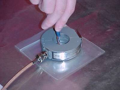
Figure 2. Discharging the Cable Through the Current Probe
In Figure 3, there is an initial current spike of over one Ampere followed by a 30 ns current of about 300 mA and then low frequency ringing. The 300 mA current and the subsequent ringing contain lots of energy, possibly enough to burn out a component. However the initial spike of current is more likely to produce upset in circuits. If the cable were connected to an actual Ethernet interface, the low frequency ringing current would be reduced by the interface transformer, but its inter winding capacitance would let much of the initial rise through. The initial current rise of Figure 3 flowing on a small wire would generate a few tens of volts per cm of drop along the wire if measured with an "ideal" differential probe. (Currently available high bandwidth, 1 GHz+, active differential probes cannot handle such a large signal and their relatively low input impedance at high frequencies would divert a large portion of the discharge current from the wire.)
Figure 3. Discharge From a 4 Meter Cable Charged to About 300V
Figure 4 shows a discharge waveform for a 1 meter cable. Notice that the first 8 ns of the waveform is about the same. After that, the ringing frequency is higher and the total energy (proportional to i2t) in the current appears lower for the short cable. The likelihood of system upset from this waveform, in large part due to the fast rising edge, is similar to the current from the 4 meter cable. However, the greater energy available from the 4 meter cable might be more likely to produce physical damage under some conditions.
Figure 4. Discharge From a 1 Meter Cable Charged to About 300V
Remember, this data was taken with 300V discharges and even so current peaks of about an Ampere were noted (bandwidth limited by the current probes). Real cables can become charged with much higher voltages. Higher voltages would result in a slower initial current rise, but with more energy in the overall waveform. That increased energy is more likely to causing damage for circuits with a low impedance to ground. For circuits with a higher impedance to ground (such as a floating transformer winding) breakdown may be induced at higher cable charging voltages..
Other articles on this website containing information on current probes or the effects of metal planes include:
More detailed information about this and other topics on this website is available from this site's subscription service and seminars.