The Elusive Glitch - Part 3
Measurement of Impulsive Fields
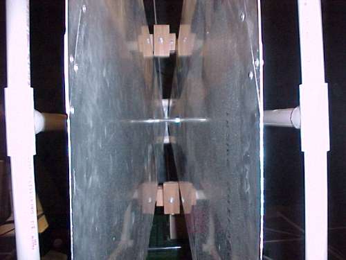
Figure 1. View Looking Into the TEM Antenna

Address: P. O. Box 1457, Los Gatos,
CA 95031
TEL:
800-323-3956/408-356-4186
FAX:
408-358-3799
Mobile: 408-858-4528
URL:
www.dsmith.org
Email: doug@dsmith.org
Figure 1. View Looking Into the TEM Antenna
As electronic equipment has become faster with clock speeds of hundreds of MHz and above, even above 1 GHz, impulsive EMI events in the environment, such as ESD, have become a major source of equipment malfunction. Events involving collisions of small pieces of metal, such as coins, are an example of one mechanism that can generate impulsive EMI.
To characterize the EMI generated by such events an antenna is needed that can accurately reproduce the time domain waveform of a fast impulse. Figure 1 shows a view looking into such an antenna, known as a TEM antenna. Figure 2 shows a view of the complete antenna. This antenna is basically a 50 Ohm tapered transmission line. A balun is located at the connection point to the coaxial cable to interface the balanced signal from the antenna to the unbalanced coaxial cable. As impulsive EMI becomes more important with faster equipment, antenna structures like this will become more important and will have a direct effect on circuit designs. Antennae like this one are being used in standards development from which requirements will be placed on circuit designs and their testing.
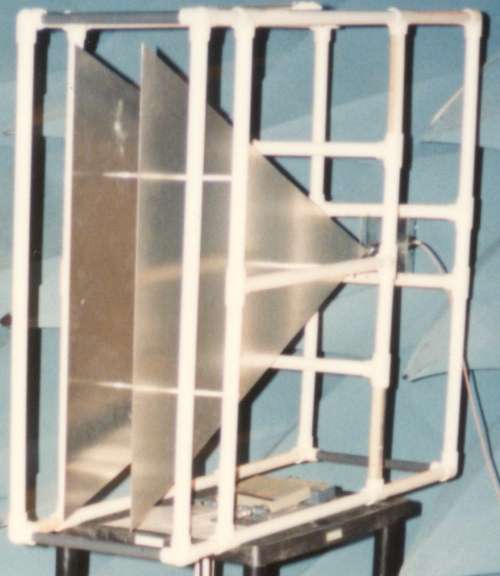
Figure 2. Overall View of TEM Antenna
The electric field strength is related to the antenna output by multiplying the antenna output by 1 meter divided by the plate separation at the front of the antenna. For the antenna in Figure 2, the antenna output is multiplied by approximately 7 to get the electric field strength. Figure 3 shows the output of the antenna resulting from the collision of two coins in front of the antenna that are differentially charged by a few hundred volts. Notice that one pulse appears, with no ringing. The electric field amplitude is about 7/m x 2.5 Volts or about 17.5 Volts/meter, a significant signal. Another way to think of the signal strength is that it delivered 1/8 watt of peak power into the 50 Ohm load at the scope (2.5*2.5/50). Not bad for a couple of coins!
Figure 3. TEM Antenna Output for Small Metal ESD
Figure 4 below shows the output of a dipole antenna approximately 30 cm in length near an ESD event. This picture appeared in my 1999 EOS/ESD Symposium paper, Unusual Forms of ESD and Their Effects. Most antenna structures have one or more resonant frequencies and this gives them a ringing response to an impulse. In addition, many antennas designed for use in the frequency domain such as for EMC testing, have dispersive characteristics that distort fast pulses. When one sees a response like Figure 4, the antenna is suspect and must be checked. While the waveform of Figure 4 indicates the presence of an ESD event and something about the available energy, it does not give an accurate picture of the actual impulsive field that was radiated.
Figure 4. Dipole Antenna Output for Impulsive ESD
I am working with engineers from several companies to collect data using a TEM antenna in typical environments, such as server installations. This data will be published in the next year and it should prove useful to both designers of equipment and the IT, information technology, people who maintain it.
For more information see:
The waveform in Figure 3 was taken with an Agilent Infinium 54845a oscilloscope.
More detailed information about this and other topics on this website is available from this site's new subscription service and seminars.