A Static Field Powered EMI Source
![]()
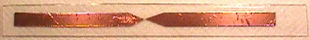
Figure 1. Spark Gap EMI Source

Address: P. O. Box 1457, Los Gatos,
CA 95031
TEL:
800-323-3956/408-356-4186
FAX:
408-358-3799
Mobile: 408-858-4528
URL:
www.dsmith.org
Email: doug@dsmith.org
![]()
Figure 1. Spark Gap EMI Source
The May, 2001 Technical Tidbit, Hidden Threats to Electronic Equipment, discussed how static fields can cause internal sparking in electronic equipment resulting in operational problems due to electromagnetic interference, EMI. The same effect can be used to make an EMI generator that produces strong, reproducible, EMI either for stressing electronic systems or just to show how easily a static field can be converted to strong EMI. Figure 1 shows a spark gap and antenna formed by two pieces of copper foil tape placed upon a piece of clear plastic and covered with clear packing tape. Figure 2 shows a close-up of the spark gap itself. The pattern in the background is from a paper towel under the plastic. Several attempts at positioning the foil of the left side of the gap were necessary before a close enough spacing was achieved. This accounts for the rippled appearance of the foil on the left.
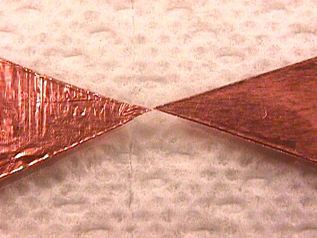
Figure 2. Close-up of Spark Gap
To see how this structure works, place an AM radio tuned to an empty frequency within a meter of the device. Charge a styrofoam cup by rubbing it on clothing. If you can feel the hair on your arm arm stand up when the cup is held near your arm, there is a charge of several thousand Volts on it. Bring the charged cup close to the foil on one side of the gap. You will hear successive "pops" in the radio as the cup approaches the foil and (usually) the same number of pops as the cup is removed. This happens because sparks form in the gap in response to the static charge on the cup as described in Hidden Threats to Electronic Equipment. In a dark room, you can actually see the sparks in the gap as a charge is induced on the foil by the proximity of the cup!
The characteristics of a spark are determined mostly by the arc length. A number of factors influence arc length including voltage, speed of approach for moving pieces, and atmospheric conditions. The gap in Figure 2 is a fraction of a millimeter. For such a small gap, the risetime of the current when a spark forms is very fast and the current waveform is repeatable. Low voltage ESD events, a few hundred volts or less, can have risetimes in the tens of picoseconds range. A high voltage spark with a relatively long arc length results in a slower risetime of the current and the current waveform may vary between successive sparks. A 10 kV discharge may have risetimes of tens of nanoseconds. The resultant di/dt for a small, low voltage, arc is higher than for high voltage events and in many instances is more likely to result in a system upset.
The packing tape over the copper foil and gap seals the environment of the spark and helps stabilize its characteristics against humidity and contamination from the environment. The copper foil forms an antenna to radiate the high frequency energy generated by a spark.
To get an appreciation of how intense the EMI generated by this structure is, short a scope probe with its ground lead and connect a one meter wire to the probe as shown in the July, 1999 Technical Tidbit "The Shorted Scope Probe." The one meter wire and probe cable shield acts as an antenna while the probe measures the voltage across the ground lead due to ESD induced currents flowing on this antenna. When a spark is induced in the gap of Figure 1, the radiated field can produce several volts across a 15 cm scope probe ground lead at a distance of one meter. You will notice that pops in the radio are accompanied by scope traces of nearly identical waveforms. The polarity of the waveforms as a charge approaches the foil is inverted from the waveforms as the charge is withdrawn.
So what is this engineering "toy" good for? Besides being a good science project for a student in school, it can be used to debug system ESD immunity problems. Just hold the "EMI Generator" near your system and induce sparks. It does not matter how the spark is induced, once the spark jumps, the radiated fields are pretty much the same as arc length and antenna structure is constant. Confirm that a spark is jumping by listening for pops in an AM radio. If you can induce a system problem within the distance of a meter or so, you may have interesting field problems. If your equipment does not react to the EMI generator held nearby, count your blessings! The system will be less likely to respond to EMI in the field.