 |
 |
 |
|
|
|
|
 |
 |
 |
|
|
|
|

Address: P. O. Box 1457, Los Gatos,
CA 95031
TEL:
800-323-3956/408-356-4186
FAX:
408-358-3799
Mobile: 408-858-4528
URL:
www.dsmith.org
Email: doug@dsmith.org
|
|
|
|
|
|
|
|
|
|
|
|
|
|
|
|
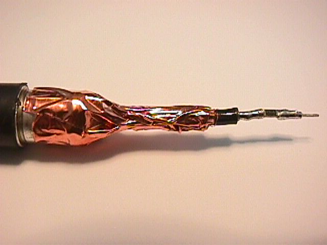
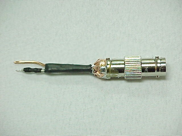
Click on the pictures to zoom in and click again to return to this page.
Construction:
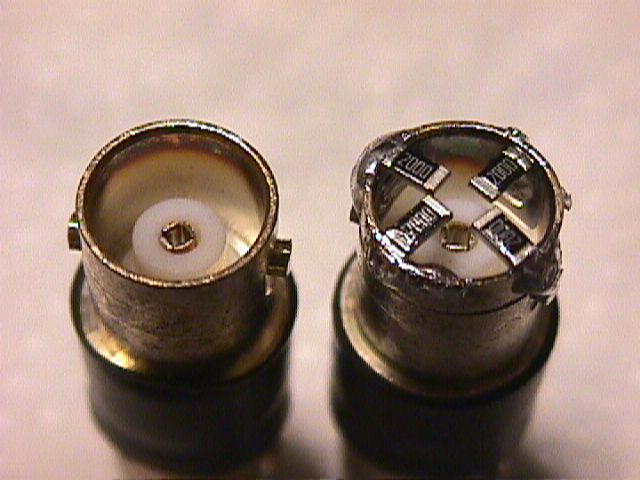
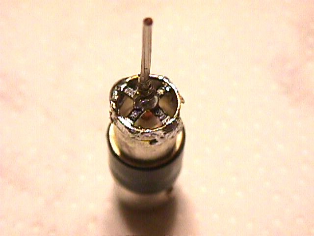
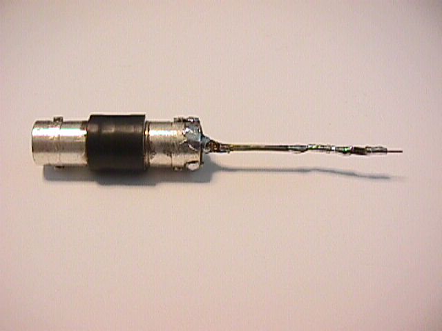
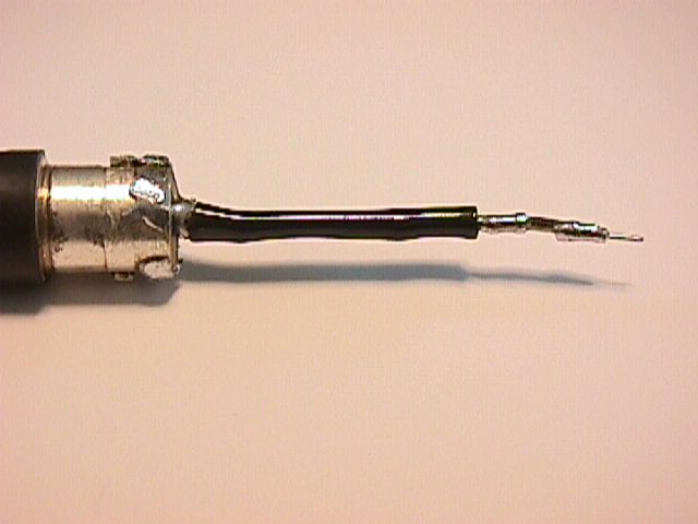
The probe shown above is a home built DC to 1GHz probe that works as well commercial probes costing hundreds of dollars. This probe and its properties are discussed at length in my seminars and in talks at various IEEE EMC Society presentations. To build one, follow these steps:
Theory of Operation:
The probe is a voltage divider comprised of the 976 Ohm tip resistor
and a 25 Ohm load (the 50 Ohm termination in parallel with the 50 Ohm characteristic
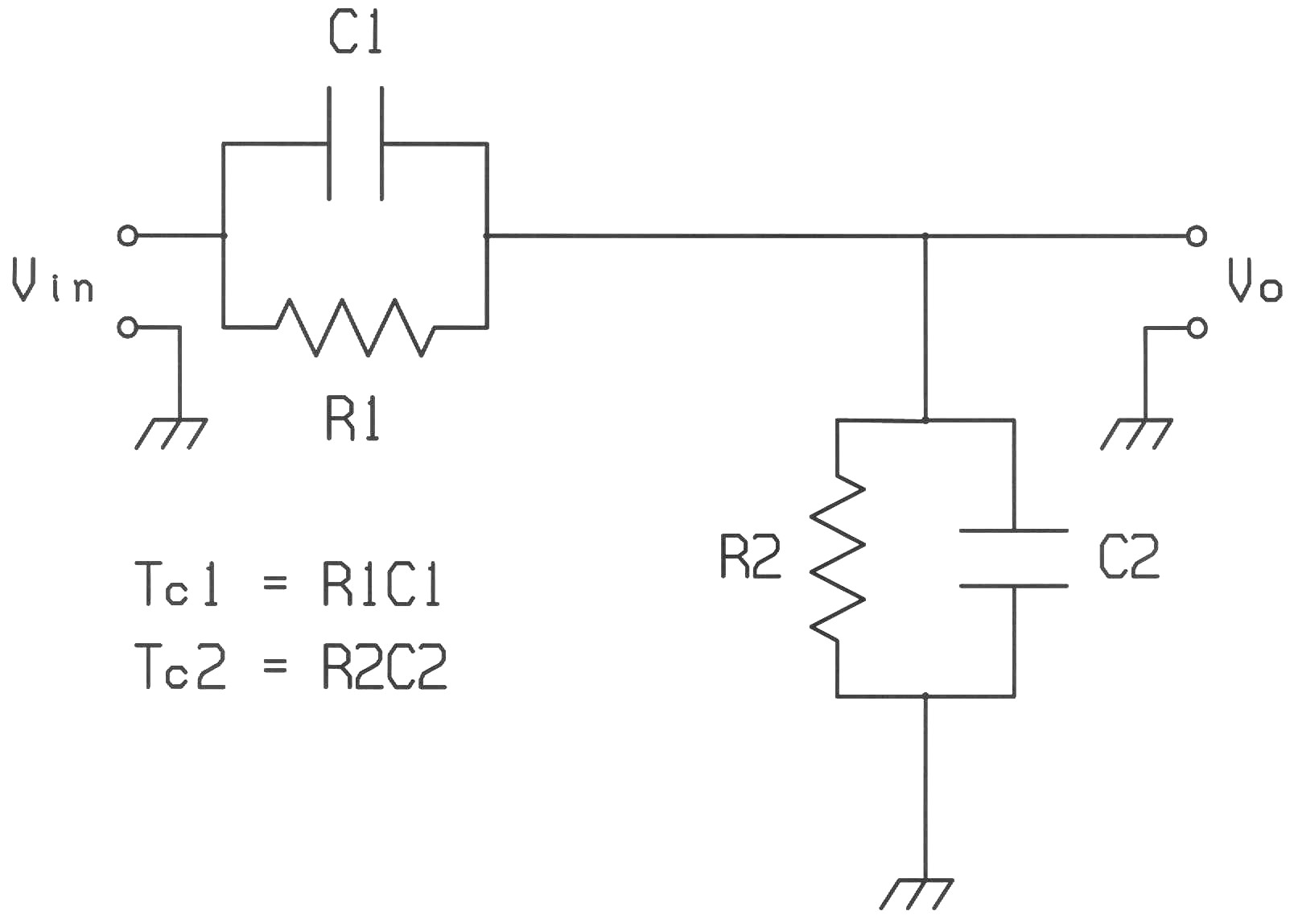
impedance of the coaxial cable). However, at 1 GHz the parasitic capacitance
of the resistors causes the divider to become an RC voltage divider as
shown in Figure 1 below. R1C1 is the 976 Ohm tip resistor with its parasitic
capacitance while R2C2 is comprised of the 25 Ohm load and the parasitic
capacitance of the 200 Ohm resistors.
 |
|
|
The transfer function for the RC voltage divider is given by:
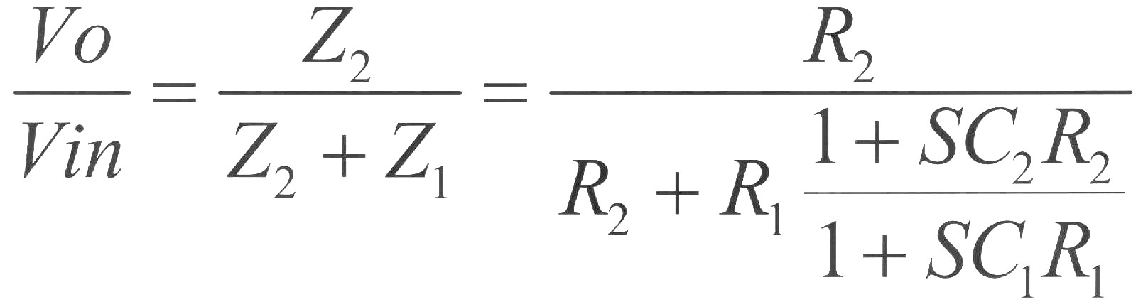 |
Note that when R1C1 equals R2C2 all frequency dependence drops out of the transfer function and the divider behaves like a simple resistive divider. Since R1, 976 Ohms, is about 39 times the value of R2, 25 Ohms, then C2 must be about 39 times the value of C1. It is very unlikely that the four 200 Ohm resistors will have that much capacitance so we must add extra capacitance across the 200 Ohm resistors. If the parasitic capacitance of the tip resistor is 0.1 pF, then a total of 3.9 pF of capacitance across the 200 Ohm resistors, including their parasitic capacitance, will be needed for the frequency response to be flat.
The foil serves to add the required capacitance. By trimming its length, just the right amount of capacitance can be added to give the probe a flat frequency response. Without the foil, typical surface mount resistors will give the probe about 6 dB of unwanted gain at 1 GHz.
At 1 GHz, the input impedance of the probe is dropping due to the parasitic
capacitance of the tip resistor. An unwanted gain of 6 dB at 1 GHz implies
that the parasitic capacitance of the tip resistor is becoming comparable
to its resistance of 976 Ohms. Lowered input impedance at high frequencies
becomes the main limiting factor for the useful frequency range of this
probe. To build a probe useable to higher frequencies, resistors with lower
parasitic capacitance must be used. Resistors used in microwave circuits
are typically adjusted by grinding down the thickness of the film rather
than making a cut in the film and so have lower parasitic capacitance.
These resistors should allow higher frequency response for this probe.
Because of the reduced tip resistor capacitance, less foil will be needed.
An in-depth audio format discussion of this article covering background as well as more technical details is available at: http://emcesd-p.com
If you like the information in this article and others on this website, much more information is available in my courses. Click here to see a listing of upcoming courses on design, measurement, and troubleshooting of chips, circuits, and systems.
 |
Check out my podcast containing mp3 format short tutorials, tech news and more! Just click on the microphone to see the listing
of free
audio programs. Content is added every week on technical topics so check back frequently. |